
System for generating constant speed output from variable speed input

a technology of variable speed input and output power, which is applied in the direction of speed sensing governors, electric generator control, instruments, etc., can solve the problems of wasting power or electrical energy in connection with conversion to power grid frequency, inefficient devices for converting input power at variable frequency to output power at a stable frequency, and many useful power or electrical energy generated by environmentally powered generators lost or wasted

Inactive Publication Date: 2010-12-14
DUFFEY CHRISTOPHER K +1
View PDF20 Cites 12 Cited by
  • Summary
  • Abstract
  • Description
  • Claims
  • Application Information

AI Technical Summary

Benefits of technology

"The patent describes a system for supplying output torque or energy to a driven machine at a constant or desired rotation rate. The system includes a clutch that connects the shaft of a prime mover or machine to the shaft of a driven machine. The clutch allows for the regulation of the rotation rate of the driven shaft by varying the torque generated between the two machines. The system also includes sensing and control means to regulate the torque and rotation rate. The technical effect of the patent is to provide a system for supplying constant or desired rotation rates to driven machines, ensuring synchronous generators or motors operate at a constant frequency."

Problems solved by technology

Devices for converting input power at variable frequency to output power at a stable frequency are believed to be inefficient.
As a result, it is believed that much useful power or electrical energy generated by environmentally powered generators is lost or wasted.
Inasmuch as the amount of electrical power supplied to the various power grids across the United States by environmentally powered turbines is increasing, it can be seen that much power is being wasted in connection with conversion to power grid frequencies.
Indeed, systems for efficiently supplying rotational energy or torque at a constant shaft rotation rate using energy or torque delivered by a shaft powered by any prime mover that supplies power at a rotation rate that varies are not known.

Method used


Image

  • System for generating constant speed output from variable speed input
  • System for generating constant speed output from variable speed input
  • System for generating constant speed output from variable speed input

Examples


Embodiment Construction

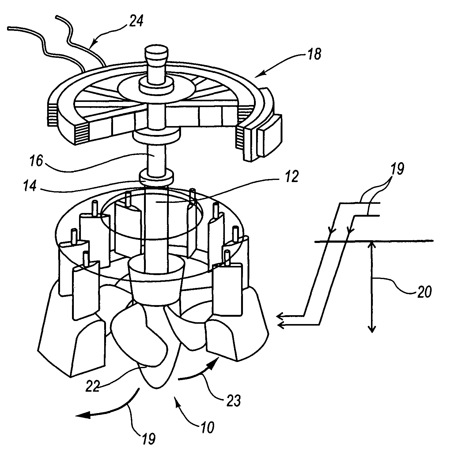
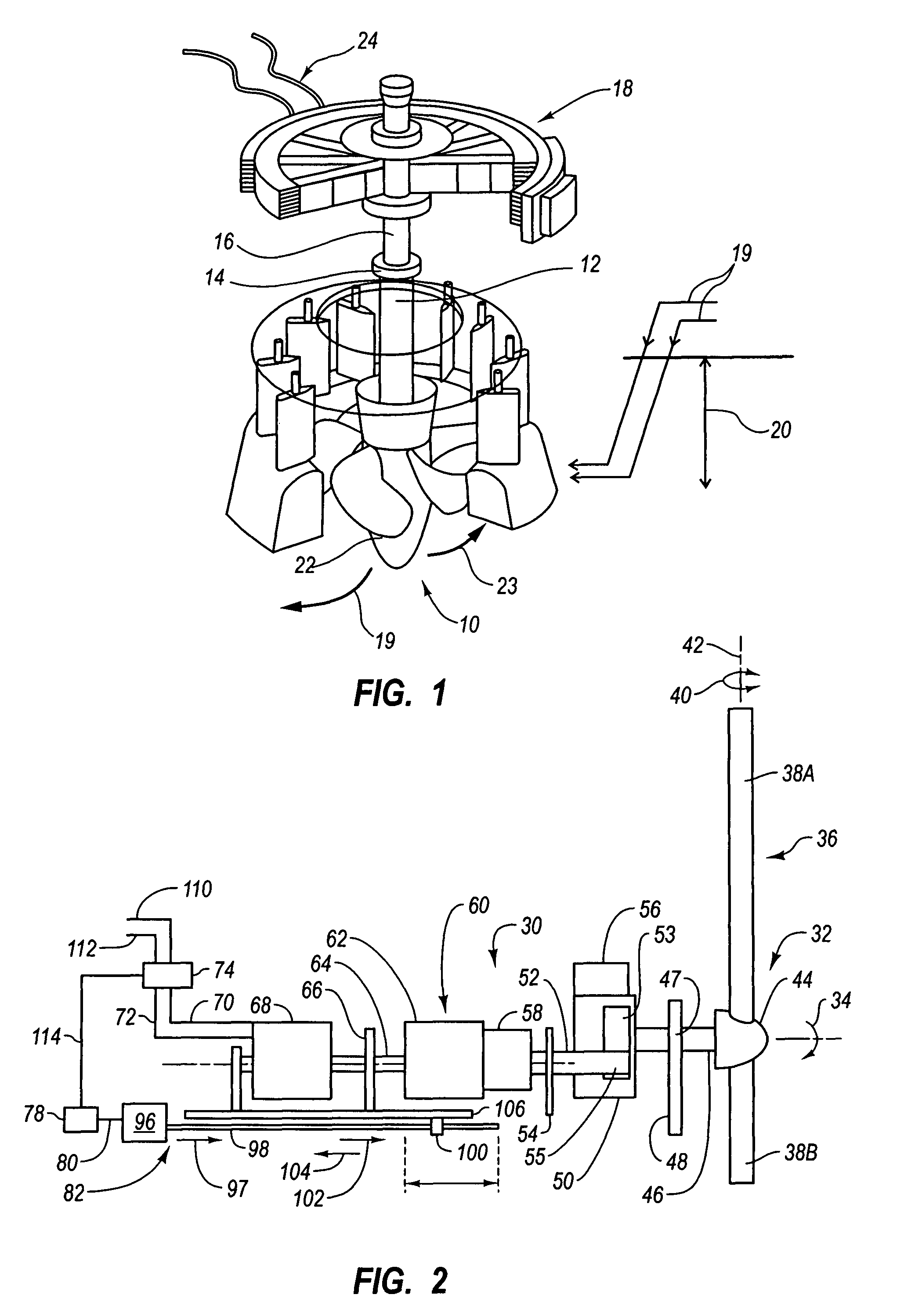
[0034]In FIG. 1, a prime mover or source of rotational torque such as water turbine 10 is connected by a lower vertical shaft 12 that rotates at different rotation rates through a clutch 14 and an upper vertical shaft 16 that rotates at a substantially constant rotation rate to a generator 18 configured to produce electricity. In operation, water 19 stored or provided at a height 20 (e.g., behind a water dam) is directed through channels or chutes to fall or flow from the height 20 to attain velocity and inertia. It is then directed through directional gates 21 and over turbine blades 22 configured to rotate 23 upon the application of force supplied by the moving water 19. Thus, the potential energy of the water stored at height 20 is converted into kinetic energy as it falls which is then converted into mechanical energy in the form of rotational torque. The rotation of the turbine blades 22 of the turbine 10 causes the lower vertical shaft 12 to rotate which in turn rotates a port...


PUM


Abstract

An input shaft rotates at variable rotation rates and is driven by a variable source of energy or power such as by the propeller of a wind-driven electrical generator. The input shaft is connected to a clutch which is connected to an output shaft and which is operable to rotate the output shaft at a preselected or constant rotation rate. The clutch has a first rotor which electromagnetically interacts with a second rotor to create a torque to cause the second rotor to rotate. The interaction of the first rotor and the second rotor may be varied electrically or mechanically to vary the torque and in turn the rotation rate of the second shaft. The shaft is preferably connected to a synchronous generator; and the rotation rate of the output shaft is controlled so that the generator supplies power at an essentially constant rotation rate.

Description

BACKGROUND OF THE INVENTION[0001]1. Field[0002]This application relates to systems that transfer or convert power or energy delivered by a prime mover into useful energy and more particularly to systems which receive power or energy in from a source that delivers power through a shaft that rotates at variable rates and generates an output at a desired rotation rate such as one that is essentially or substantially constant and even more particularly to systems that convert energy from a prime mover like a propeller driven by wind, a water turbine, or a wave turbine, into AC power.[0003]2. The Relevant Technology[0004]Wind turbines (e.g., GE Energy 1.5 mw series wind turbine found at http: / / www / gepower.com), water turbines (e.g., http: / / en.wikipedia.org) and wave turbines (e.g., Islay Wave Power Station reported by the BBC at http: / / news.bbc.co.uk / 1 / hi / sci / tech / 103148.stm) have been developed for, among other things, generating electrical power. However, because the wind speed is vari...

Claims


Application Information

Patent Timeline
Patent Type & Authority Patents(United States)
IPC IPC(8): F03D3/04
CPCF03D11/00F05B2210/16Y02E10/722F03D80/00Y02E10/72F16D43/22
Inventor DUFFEY, CHRISTOPHER K.SMITH, LESLIE R.
Owner DUFFEY CHRISTOPHER K
Learn More