Connector for connection to a module board

a technology for connecting cables and modules, applied in the direction of electrical apparatus casings/cabinets/drawers, coupling device connections, lighting and heating apparatus, etc., to prevent outside noise leakage

Inactive Publication Date: 2010-12-14
YAMAICHI ELECTRONICS
View PDF28 Cites 19 Cited by
  • Summary
  • Abstract
  • Description
  • Claims
  • Application Information

AI Technical Summary

Benefits of technology

[0010]In view of the above-described problems, the present invention has an object to provide a connector for connection to a module board including an eject mechanism selectively ejecting a module board and having the following characteristics. Specifically, the connector for connection to a module board can provide a lock mechanism for preventing disconnection or ejection of a module board at a predetermined position irrespective of the size of the module board. In addition, the connector for connection to a module board can avoid outside leakage of noise generated by a module board through a gap between a push button of the eject mechanism and a housing of an electronic device.
[0012]In the connector for connection to a module board according to the present invention, the locking member is rotatably provided in the through hole of the guide rail member that forms the module accommodating section. This allows provision of a lock mechanism for preventing disconnection or ejection of a module board at a predetermined position irrespective of the size of the module board. In addition, in the connector for connection to a module board, the collar-like portion is formed on the operation section of the eject button so as to conform to the opening of the housing provided with the wiring board, and is pressed against the inner peripheral surface around the opening of the housing during the lock state. Accordingly, the connector for connection to a module board prevents outside leakage of noise generated by the module board through a gap between the push button of the eject mechanism and the housing.

Problems solved by technology

The disposition is contrary to component standardization since the problem leads to the need of different eject mechanisms for connection to a module boards in different sizes.
This is trouble when outside leakage of noise generated by a module board is perceived as problems.

Method used


Image

  • Connector for connection to a module board
  • Connector for connection to a module board
  • Connector for connection to a module board

Examples


Embodiment Construction

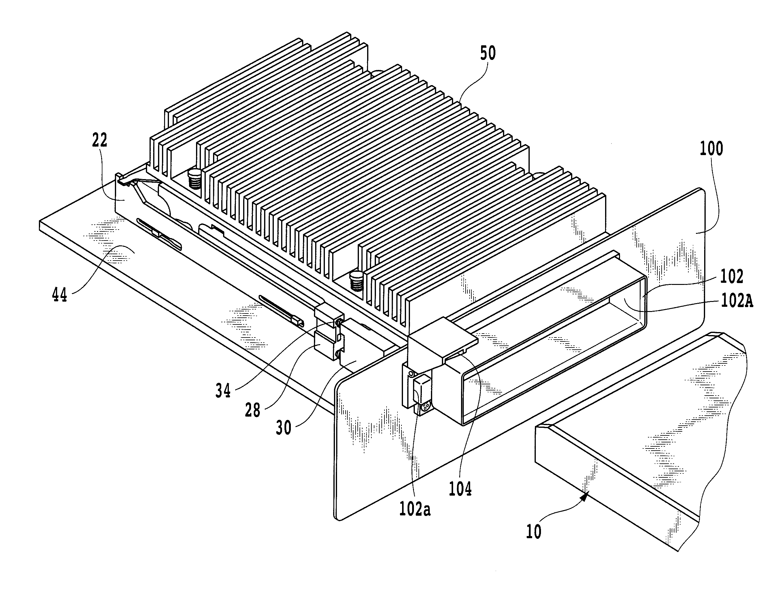
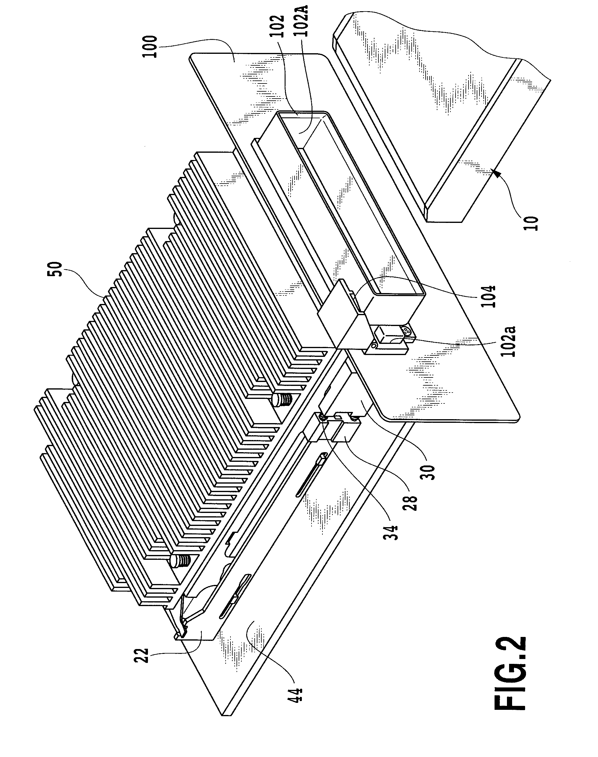
[0080]FIG. 2 shows a view showing an appearance of embodiment of a connector for connection to a module board according to the present invention, as well as a module.

[0081]In FIG. 2, multiple connectors for connection to a module board are provided in parallel at predetermined positions in a housing 100 of a predetermined electronic equipment. Note that FIG. 2 shows one of the connectors for connection to a module board as a representative example.

[0082]To each portion where a module slot (not shown) is formed in the outer peripheral surface of the housing 100, a module guide 102 is attached as shown in FIGS. 2 and 3.

[0083]Note that, as shown in FIG. 3, the module guides 102 are arranged in a line at predetermined intervals on a common plane.

[0084]Each module guide 102 formed like an approximately rectangular frame has an opening 102A in the center, in which a module 10 passes through the opening 102A at the time of insertion and withdrawal of a module board from the connector for c...


PUM


Abstract

Provided is a connector for connection to a module board including an eject mechanism selectively ejecting a module from a module accommodating section. The eject mechanism includes a locking member that has a locking nib engageable with a recess of a case of the module. The locking member is rotatably supported by a sidewall section of a guide rail member, and thus can stay in an opening of the sidewall section. An eject button of the connector for connection to a module board has an operation section provided with a flange. The flange is pressed against the inner peripheral surface of a housing of an electronic device by a biasing force of coil springs all the time except for when the operation section is pushed in.

Description

CROSS-REFERENCE TO RELATED APPLICATIONS[0001]This application claims the benefit of U.S. Provisional Patent Application No. 61 / 083,358 filed Jul. 24, 2008, which is hereby incorporated by reference herein in its entirety.BACKGROUND OF THE INVENTION[0002]1. Field of the Invention[0003]The present invention relates to a connector for connection to a module board including an eject mechanism selectively ejecting a module board.[0004]2. Description of the Related Art[0005]An expansion card such as a PC card including a module board therein is installed in an electronic device by being inserted in a card connector provided in the electronic device. The card connector has a card slot on its one end, and a PC card passes through the card slot at the time of installing the PC card. The card slot communicates with a card insertion opening provided in the outer periphery of a housing of an electronic device. In addition, such a card connector comprises an eject mechanism detachably holding a ...

Claims


Application Information

Patent Timeline
Patent Type & Authority Patents(United States)
IPC IPC(8): H05K7/20
CPCH05K5/0286H01R12/724H01R13/633H01R24/60
Inventor ITO, TOSHIYASU
Owner YAMAICHI ELECTRONICS
Why Eureka
Try Eureka