
Medical device with procedure improvement features

a technology of medical devices and features, applied in the field of medical devices with procedure improvement features, can solve the problems of difficulty in aligning or orientating the subject device, and difficulty in actuating a member, so as to increase effectiveness and efficiency, the effect of increasing effectiveness and efficiency

Active Publication Date: 2010-12-14
BOSTON SCI SCIMED INC
View PDF419 Cites 49 Cited by
  • Summary
  • Abstract
  • Description
  • Claims
  • Application Information

AI Technical Summary

Benefits of technology

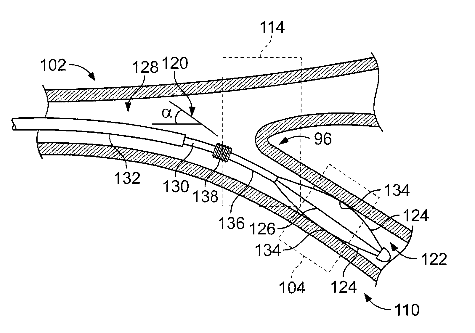
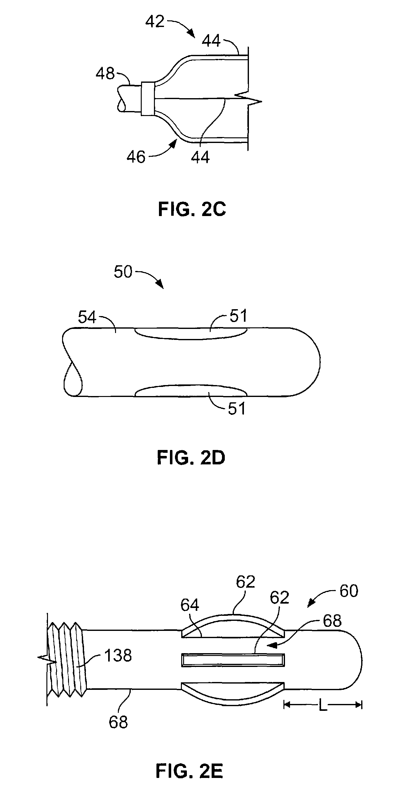
The present invention provides medical devices that can be easily adjusted or realigned to better position an active element in contact with tissue. This is achieved through the use of a junction or joint that allows for flexibility in the positioning of the active element. The junction can be adjusted or controlled with minimal effort by a physician, which increases efficiency and effectiveness in carrying out a medical procedure. The invention also includes methods for minimizing misalignment and friction between the device and the anatomy, which can lead to improved accuracy in active member placement. The invention can be used in various parts of the body where tortuous anatomy or misaligned pathways are present. Additionally, the invention includes surface modifications to reduce friction and contact wear between the device and the anatomy.

Problems solved by technology

However, in any case where a medical practitioner advances a device to a remote operative site (e.g., open surgical procedure with a remote operative site, percutaneous access, and / or access via an open body conduit) alignment or orientation difficulties with the subject device may arise.
Tortuous anatomy may also create challenges when the particular treatment device requires mechanical actuation of the treatment portion.
In particular, attempting to actuate a member may be difficult if the actuation force applied at the operator's hand-piece must translate to the distal end of the device.
Yet, if the access path is misaligned from the treatment site, then difficulties may arise in attempting to and achieve uniform contact (or near contact) at the desired treatment site.
However, the tortuous nature of the airways may cause significant bending and / or flexure of the distal end of the device.
The flexure may impose non-uniform forces on the flexible electrode as a result of the airway wall.
These non-uniform forces may result in distortion of one or more of the flexible electrodes.
Aside from the possibility of damaging the device, distortion of the device may impact the treatment.
For many treatment devices, the distortion of the energy transfer elements might cause variability in the treatment effect.
This directly affects the amount of heat in the tissue.
In any number of cases, variability of the energy transfer / tissue interface causes variability in treatment results.
The consequential risks range from an ineffective treatment to the possibility of patient injury.
Therefore, distortion of the transfer element or elements increases the procedure time when the practitioner spends an inordinate amount of time adjusting a device to compensate for or avoid such distortion.
Such action becomes increasingly problematic in those cases where proper patient management limits the time available for the procedure.
For example, if a patient requires an increasing amount of medication (e.g., sedatives or anesthesia) to remain under continued control for performance of the procedure, then a medical practitioner may limit the procedure time rather than risk overmedicating the patient.
Subsequently, increasing the number of sessions poses additional consequences on the part of the patient in cost, the residual effects of any medication, etc.

Method used


Image

  • Medical device with procedure improvement features
  • Medical device with procedure improvement features
  • Medical device with procedure improvement features

Examples


Embodiment Construction

[0052]It is understood that the examples below discuss uses in the airways of the lungs. However, unless specifically noted, the invention is not limited to use in the lung. Instead, the invention may have applicability in various parts of the body. Moreover, the invention may be used in minimally invasive procedure, or open surgical procedures where orientation and alignment features are desired.

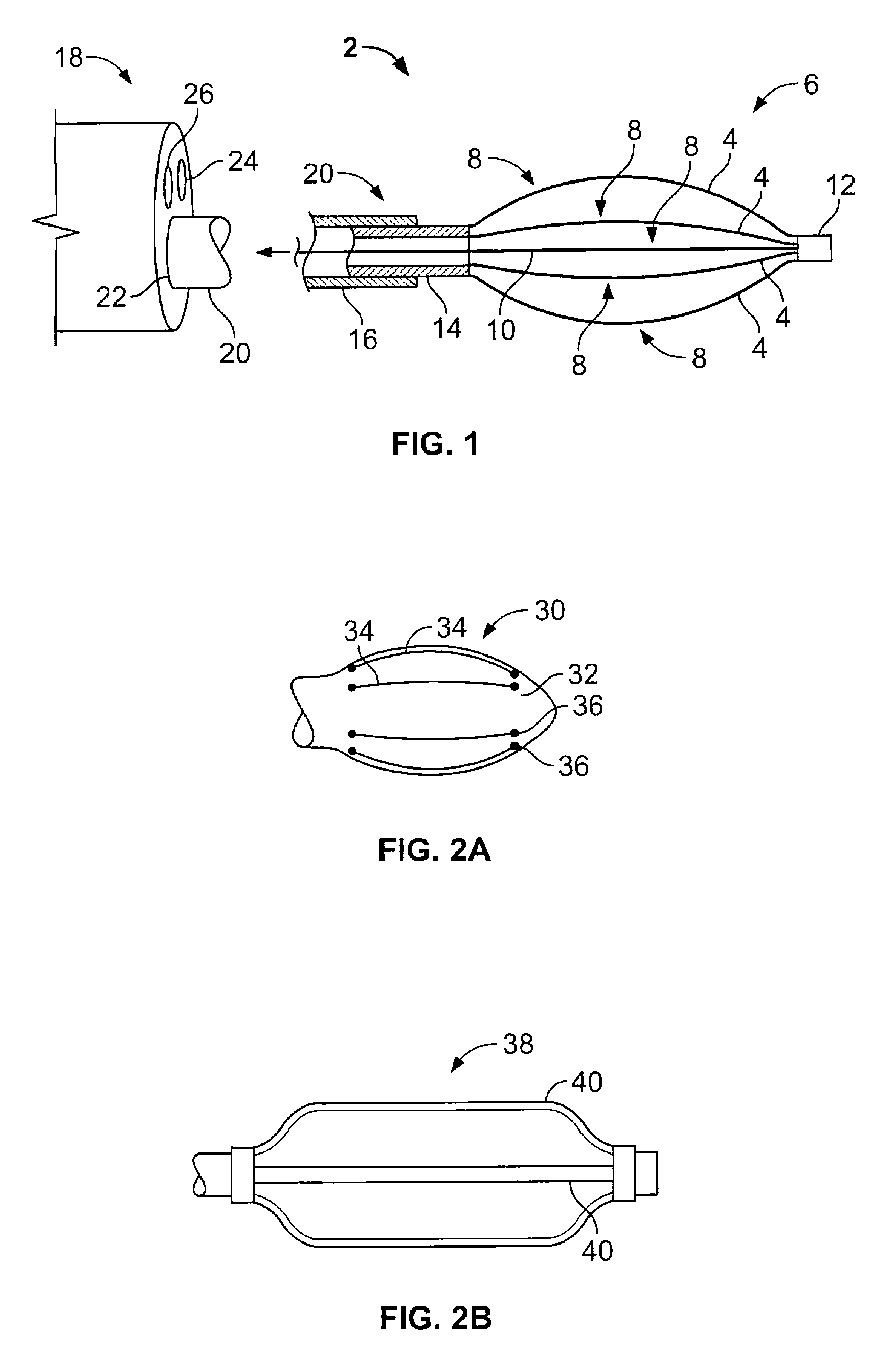
[0053]Generally speaking, the invention includes medical devices including an elongate member with an active distal end, where a junction is provided between the two structures. The junction permits rotation or angular adjustment of the active end relative to the elongate member in order to better situate the active end for contacting the tissue wall of a cavity or passageway give misalignment between such structure and an access pathway. The invention includes methods of using such devices, where the device permits adjustment or realignment improved active member orientation or placement. ...


PUM


Abstract

This relates to methods and devices for achieving contact between the wall of a cavity or passageway and a medical device under conditions in which an access path and the subject anatomy are not aligned.

Description

CROSS-REFERENCE TO RELATED APPLICATION[0001]This application is a continuation of PCT Application Number PCT / US2005 / 040378, filed Nov. 7, 2005, which claims the benefit of U.S. Provisional Patent Application No. 60 / 625,256, filed Nov. 5, 2004 and U.S. Provisional Patent Application No. 60 / 650,368, filed Feb. 4, 2005, the contents of which are incorporated herein in their entirety.BACKGROUND OF THE INVENTION[0002]It is well understood that “minimally invasive” as opposed to open surgical approaches often offer benefits in terms of decreased patient trauma, increased patient acceptance, improved recuperation time, and lower associated costs—both monetarily and in terms of other metrics. Accordingly, instances of minimally invasive procedures are increasingly common.[0003]However, in any case where a medical practitioner advances a device to a remote operative site (e.g., open surgical procedure with a remote operative site, percutaneous access, and / or access via an open body conduit) ...

Claims


Application Information

Patent Timeline
Patent Type & Authority Patents(United States)
IPC IPC(8): A61F7/12
CPCA61B18/1492A61B18/082A61B2018/00214A61B2018/00267A61B2018/00541A61B2018/1435
Inventor KAPLAN, GARY S.DANEK, CHRISTOPHER J.WIZEMAN, WILLIAM J.DALBEC, TIM R.
Owner BOSTON SCI SCIMED INC
Learn More