Animal trap

Inactive Publication Date: 2010-12-21
KURACHI STEVE T
View PDF86 Cites 35 Cited by
  • Summary
  • Abstract
  • Description
  • Claims
  • Application Information

AI Technical Summary

Problems solved by technology

However, movement of the trip arm(s) in the opposite direction, i.e., toward the gate, closes a switch and causes the drop gate to fall, capturing the animals within the entry path and enclosure.

Method used


Image

  • Animal trap
  • Animal trap
  • Animal trap

Examples


Embodiment Construction

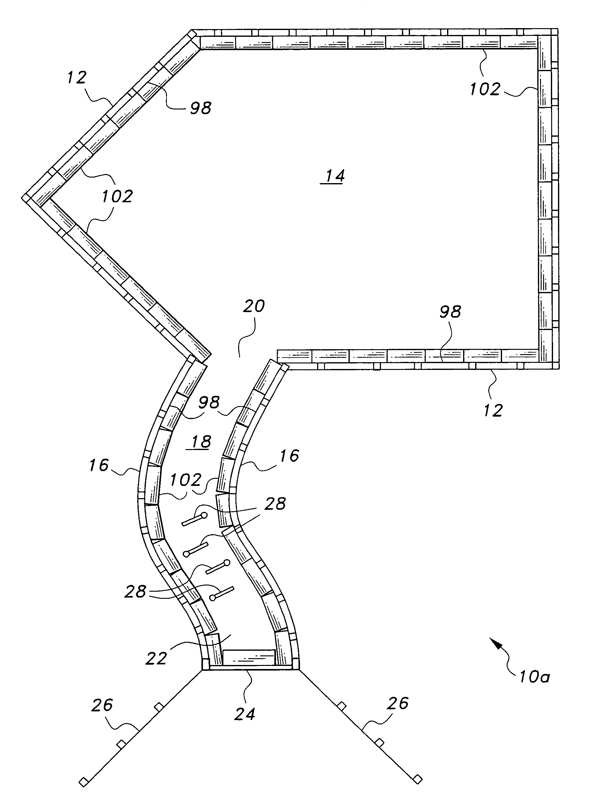
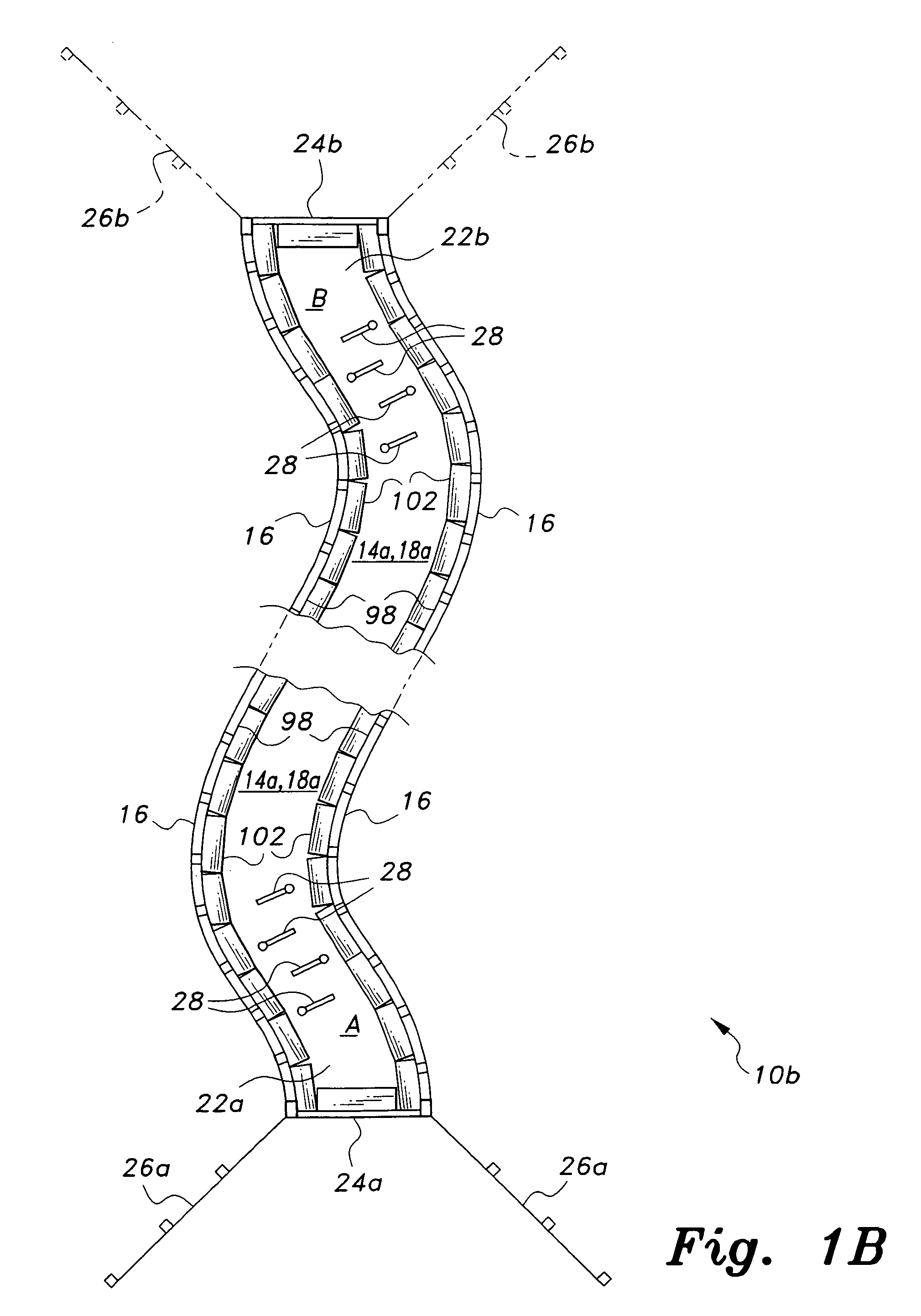
[0022]The animal trap may encompass a relatively large area (e.g., a large fraction of an acre, more or less) and has an enclosure area and an entry path leading into the enclosure area, generally as shown in FIG. 1A. The entry path may be established along an existing game trail, or otherwise laid out as desired. The entry path has an enclosure end opening into the enclosure, and an opposite entry end selectively closed by an automated drop gate actuated by the passage of animals in the exit direction through the entry path. This configuration allows a large number of animals to enter the trap through the entry path without tripping the gate and closing off entry to the trap, but closes the gate when one of the animals reverses its path and attempts to leave the trap. Alternatively, the trap enclosure may comprise a length of game trail or the like, with fencing set up along the sides of the trail and gates and their corresponding trip arms set up at each end of the fenced section,...


PUM


Abstract

The animal trap includes an enclosure for containing a number of relatively large animals. An entry path (game trail, etc.) extends from the enclosure to an automated drop gate at the entrance, or may comprise the enclosure with a gate at each end. At least one double articulated trip arm is placed along the entry path. The trip arm does not actuate the gate when moved toward the enclosure, i.e., when animals pass through the entry path from the drop gate entrance to the enclosure. However, animals passing in the opposite direction move the trip arm(s) toward the gate, causing at least one trip arm to close a circuit and drop the gate to close the trap. The trap is thus configured to capture a number of herd animals, e.g., wild pigs, passing from the gate toward the enclosure, before one of the animals turns back and trips the gate.

Description

BACKGROUND OF THE INVENTION[0001]1. Field of the Invention[0002]The present invention relates generally to hunting and trapping. More specifically, the present invention comprises an animal trap having a drop gate at the entrance and an elongate pathway extending therefrom, with a series of double articulating trip arms disposed within the pathway.[0003]2. Description of the Related Art[0004]Animal traps and trapping have been known since the earliest of times. Such traps range in size and complexity from very small traps intended to capture and / or kill a mouse or other animal of similar size, up to large enclosures intended to capture large herd animals. These traps may be further subdivided into traps requiring human attention and observation, and automatically operating traps requiring no human action during their operation.[0005]In the case of larger traps for herd animals, such traps generally require the presence and actions of human operators to close off a relatively narrow ...

Claims


Application Information

Patent Timeline
Patent Type & Authority Patents(United States)
IPC IPC(8): A01M23/00A01M23/38A01M23/20A01M23/08
CPCA01M23/08A01M23/20
Inventor KURACHI, STEVE T.
Owner KURACHI STEVE T
Why Eureka
Try Eureka