Barrier sealing system for centrifugal compressors

a centrifugal compressor and sealing system technology, applied in the direction of machines/engines, liquid fuel engines, positive displacement liquid engines, etc., can solve the problems of lubricating oil supplied to one or more radial bearings of the rotatable shaft that tend to wick along the rotor shaft, foul the tip surfaces of dry gas seals, and barrier seals that do not effectively prevent oil migration

Active Publication Date: 2010-12-21
NUOVO PIGNONE TECH SRL
View PDF15 Cites 28 Cited by
  • Summary
  • Abstract
  • Description
  • Claims
  • Application Information

AI Technical Summary

Problems solved by technology

Lubricating oil supplied to one or more radial bearings of the rotatable shaft often tend to wick along the rotor shaft and foul the tip surfaces of the dry gas seal.
However, the barrier seals do not effectively prevent migration of oil in case of reduced buffer gas flow.
For example, the barrier seals do not effectively prevent migration of oil from the bearing to the dry gas seal if the flow under the seals is relatively small compared with the effective clearances of the seals.
Moreover, the consumption of the separation gas between the pair of seals is also increased.

Method used


Image

  • Barrier sealing system for centrifugal compressors
  • Barrier sealing system for centrifugal compressors
  • Barrier sealing system for centrifugal compressors

Examples


Embodiment Construction

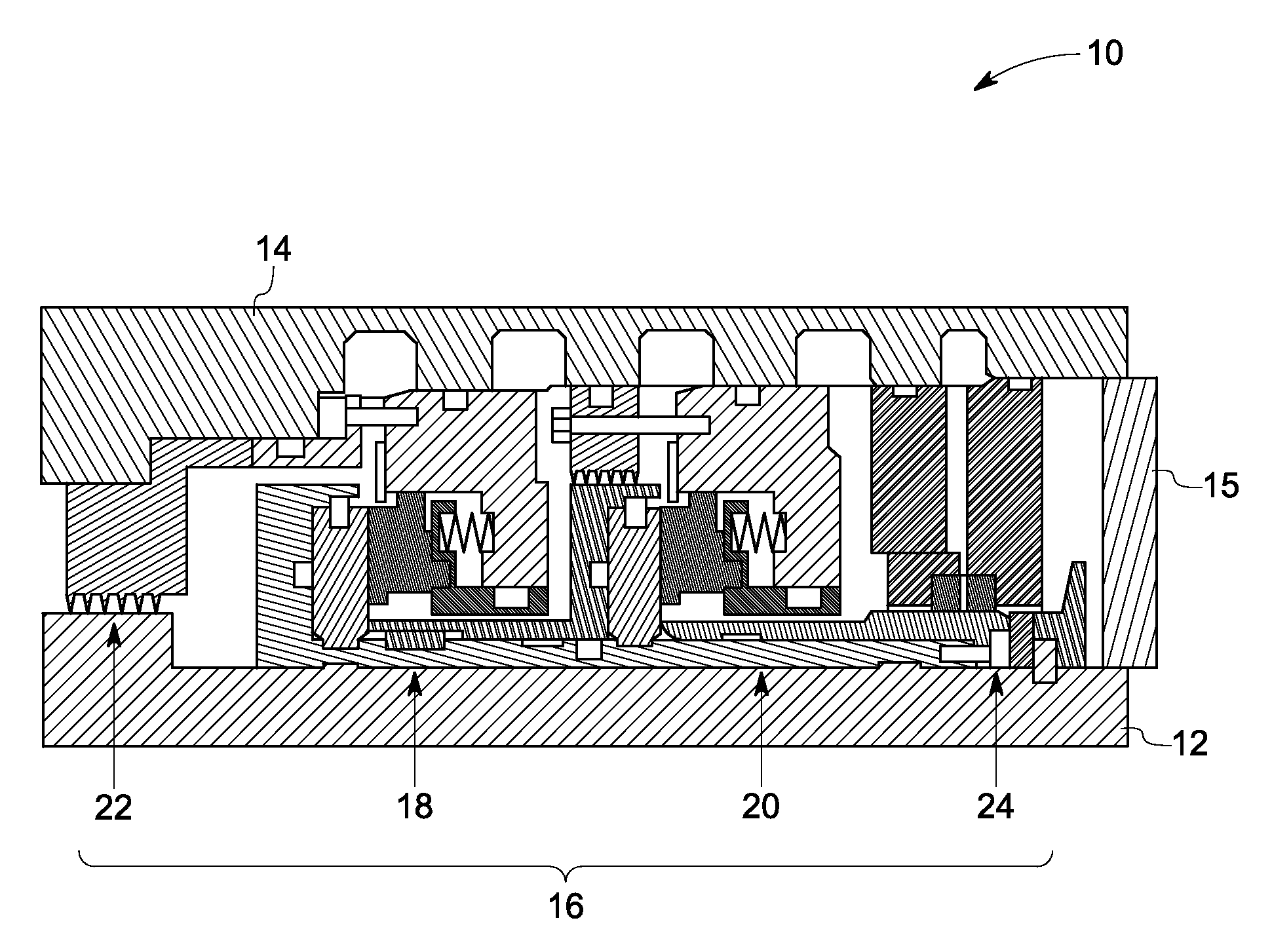
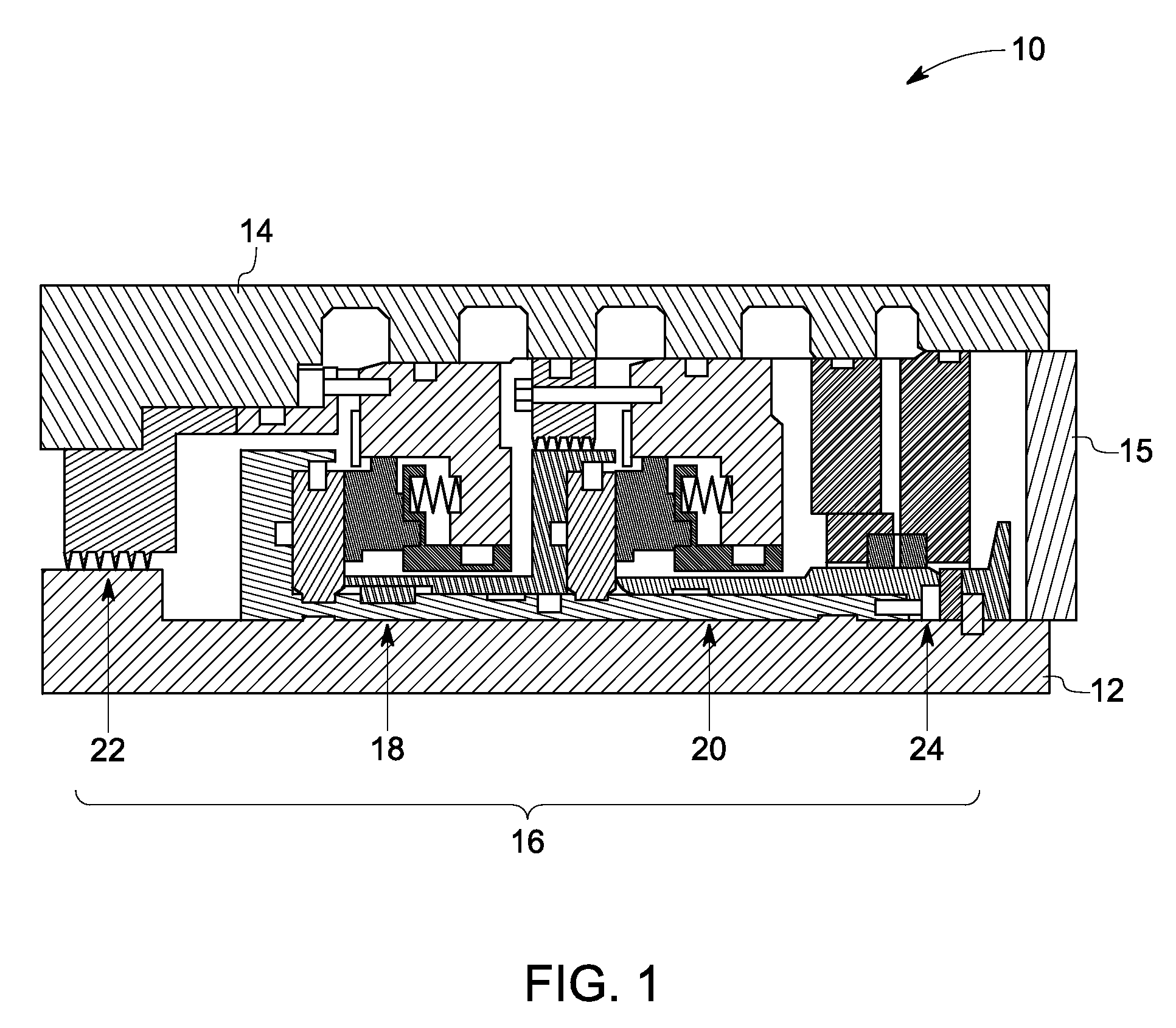
[0014]As discussed in detail below, embodiments of the present invention provide a rotary machine having a sealing device disposed between a machine rotor and a machine stator. The sealing device includes a dry gas seal, a first seal disposed on a first side between the dry gas seal and a bearing provided to the machine rotor, and a second seal disposed on a second side between the first seal and the bearing. In some exemplary embodiments, the first seal comprises a brush seal including non-metallic fibers. In some exemplary embodiments, the second seal comprises a brush seal. In some exemplary embodiments, the first and second seals may comprise brush seals that each include a plurality of non-metallic fibers. The first and second seals are configured to prevent leakage of oil towards the dry gas seal. In certain embodiments, other seals such as labyrinth seals or carbon face seals are used in conjunction with the first and second seals. Usage of non-metallic fibers in particular i...


PUM


Abstract

A rotary machine includes a machine rotor, a bearing coupled to the machine rotor, a machine stator, and a sealing device disposed between the machine rotor and the machine stator. The sealing device includes a dry gas seal and first and second seals disposed between the dry gas seal and the bearing. One or both of the first and second seals includes a brush seal or more specifically a brush seal including a plurality of non-metallic fibers.

Description

BACKGROUND[0001]The disclosed embodiments relate generally to rotary machines and, more particularly, to sealing systems for interfaces between rotating and stationary components.[0002]Rotary machines, such as centrifugal compressors, often use dry gas seals to limit leakage of a process gas along a rotatable shaft to the atmosphere. Lubricating oil supplied to one or more radial bearings of the rotatable shaft often tend to wick along the rotor shaft and foul the tip surfaces of the dry gas seal. Barrier seals (also referred to as “tertiary seals”) are provided between the dry gas seals and the radial bearing to prevent migration of oil towards the dry gas seals. Typically, the barrier seal includes a pair of seals with a gas flow path provided between the pair of seals. The barrier seals may include labyrinth seals, carbon face seals, metallic brush seals, or the like.[0003]However, the barrier seals do not effectively prevent migration of oil in case of reduced buffer gas flow. F...

Claims


Application Information

Patent Timeline
Patent Type & Authority Patents(United States)
IPC IPC(8): F01D11/02F16J15/44
CPCF01D11/001F01D11/04F01D25/16F04D29/102F16J15/3288F16J15/006F05D2250/25F05D2240/56F05D2250/15F04D17/10F04D29/023F04D29/083F04B39/00
Inventor LUSTED, RODERICK MARKWOLFE, CHRISTOPHER EDWARDRUGGIERO, ERIC JOHNMARIOTTI, GABRIELE
Owner NUOVO PIGNONE TECH SRL
Why Eureka
Try Eureka