Light-emitting diode driving circuit and secondary side controller for controlling the same

a driving circuit and diode technology, applied in the direction of electric variable regulation, process and machine control, instruments, etc., can solve the problems of affecting the accuracy of dimming control, increasing and burning of these leds, so as to reduce the cost of the led driving circuit and simplify the layout of the printed circuit board. , the effect of small voltage variation

Inactive Publication Date: 2010-12-21
NIKO SEMICON
View PDF13 Cites 112 Cited by
  • Summary
  • Abstract
  • Description
  • Claims
  • Application Information

AI Technical Summary

Benefits of technology

[0005]A primary object of the present invention is to provide an improved LED driving circuit that enables an LED module to maintain a basic voltage at two ends thereof when the LED module is dimmed, so as to ensure that there is only a relatively small voltage variation of the LED module during dimming, and it is not necessary for the LED driving circuit to consider the output voltage rising time or additionally include an output current limiting circuit for protecting the LEDs against the risk of damage. Therefore, the cost of the LED driving circuit may be reduced and the layout on a printed circuit board (PCB) may be simplified.

Problems solved by technology

This condition surely would dangerously cause burnout of these LEDs.
However, the provision of the voltage ramp-up control circuit not only increases the cost of the LED driving circuit, but also increases the transient time of voltage variation during the dimming operation to thereby adversely affect the accuracy in dimming control.

Method used


Image

  • Light-emitting diode driving circuit and secondary side controller for controlling the same
  • Light-emitting diode driving circuit and secondary side controller for controlling the same
  • Light-emitting diode driving circuit and secondary side controller for controlling the same

Examples


first embodiment

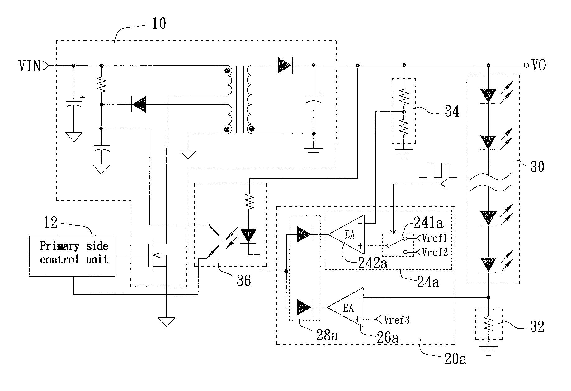
[0016]The secondary side control unit 20a includes a voltage detection signal processor 24a, a current detection signal processor 26a, and a signal selection circuit 28a. The voltage detection signal processor 24a receives the voltage detection signal and the dimming signal, and generates a voltage processing signal according to the received signals. The current detection signal processor 26a receives the current detection signal and generates a current processing signal. The signal selection circuit 28a receives the voltage processing signal and the current processing signal, and selectively outputs one of the voltage processing signal and the current processing signal, depending on the levels of the two signals. In the illustrated first embodiment, the dimming signal is a pulse signal, which is input to the voltage detection signal processor 24a for regulating the level of the voltage processing signal output by the voltage detection signal processor 24a.

[0017]The voltage detecti...

third embodiment

[0028]In the third embodiment, when the pulse signal output by the DC-to-pulse converter 281b is at a first level representing “OFF”, the signal selector 283b outputs the voltage detection signal. Therefore, the LED driving circuit operates in the constant voltage mode, and the output voltage drops to approximately the threshold voltage of the LED module 30. At this point, the LED module 30 is close to not emitting light. On the other hand, when the pulse signal selected and output by the DC-to-pulse converter 281b is at a second level representing “ON”, the signal selector 283b selects to output the current detection signal. Therefore, the LED driving circuit operates in the constant current mode, the output voltage rises for the current flowing through the LED module 30 to stably maintain at a preset current value, and the LED module 30 emits light stably.

[0029]As having been mentioned above, the present invention may be implemented by switching between a constant current and a mi...

fourth embodiment

[0030]In the fourth embodiment, when the dimming signal DIM is at a first level representing “OFF”, the signal selector 28c selects to output the minimum duty cycle signal. Through the properly set minimum duty cycle, the control signal output by the primary side control unit 12c according to the minimum duty cycle signal has a very small duty cycle, so that the energy transmitted from the conversion circuit 10 to the secondary side is approximately sufficient for maintaining the basic energy loss by the circuit elements other than the LED module 30. In other words, the driving voltage stops dropping when it is approximately the threshold voltage of the LED module 30, and maintains around a voltage. At this point, the LED module 30 is close to not emitting light. On the other hand, when the dimming signal DIM is at a second level representing “ON”, the signal selector 28c selects to output the current detection signal. Therefore, the LED driving circuit operates in the constant curr...


PUM


Abstract

A light-emitting diode (LED) driving circuit and a secondary side controller for controlling the same control an output voltage of the LED driving circuit at a first driving voltage or a second driving voltage. When the output voltage is controlled at the first driving voltage, an LED module driven by the LED driving circuit is in a stably lighting state; and when the output voltage is controlled at the second driving voltage, the output voltage is approximately a threshold voltage of the LED module but higher than zero volt, so that the LED module is close to not emitting light. Therefore, in a dimming operation, the variation of voltage applied across the LED module is smaller than that in the conventional LED driving circuits to thereby protect the LED module against an excessive voltage stress and avoid the problem of inaccurate dimming.

Description

FIELD OF THE INVENTION[0001]The present invention relates to a light-emitting diode (LED) driving circuit and secondary side controller for controlling the same that provides the dimming function, and more particularly to an LED driving circuit and secondary side controller for controlling the same that is able to control the LED driving voltage at a first driving voltage and a second driving voltage.BACKGROUND OF THE INVENTION[0002]Please refer to FIG. 1 that is a diagram of a conventional Buck converter for driving light-emitting diode (LED). When the transistor switch Q2 is turned on, current is supplied from the power source V4 and flows through the transistor switch Q2 to store energy in the inductor L1 and the capacitor C, meanwhile the current supplies energy to LEDs D2, D5 for the same to emit light. When the transistor switch Q2 is turned off, energy is released from the inductor L1 and the capacitor C4 to the LEDs D2, D5 for the same to emit light continuously. The current...

Claims


Application Information

Patent Timeline
Patent Type & Authority Patents(United States)
IPC IPC(8): H05B37/02
CPCH05B33/0815H05B33/0851Y02B20/341H05B45/10Y02B20/30H05B45/385H05B45/3725
Inventor LENG, CHUNG-MING
Owner NIKO SEMICON
Why Eureka
Try Eureka