Eureka AIR delivers breakthrough ideas for toughest innovation challenges, trusted by R&D personnel around the world.

Transmission screen

a transmission screen and back projection technology, applied in the field of transmission screens, can solve the problems of inability to inability to substantially see the other side of the transmission screen, and the meaning of the show window is lost, and achieve excellent see-through properties, wide viewing angles, and excellent see-through properties

Inactive Publication Date: 2010-12-21
KIMOTO CO LTD
View PDF10 Cites 4 Cited by
  • Summary
  • Abstract
  • Description
  • Claims
  • Application Information

AI Technical Summary

Benefits of technology

[0014]The transmission screen of the present invention can simultaneously exhibit conflicting performances, that is, an excellent see-through property and wide viewing angle. When it is stuck up on a show window, commercial articles can be seen from the outside in that state, because the transmission screen of the present invention has an excellent see-through property, and it can provide marked advertising effect as a screen having a wide viewing angle without degrading the function of the show window.
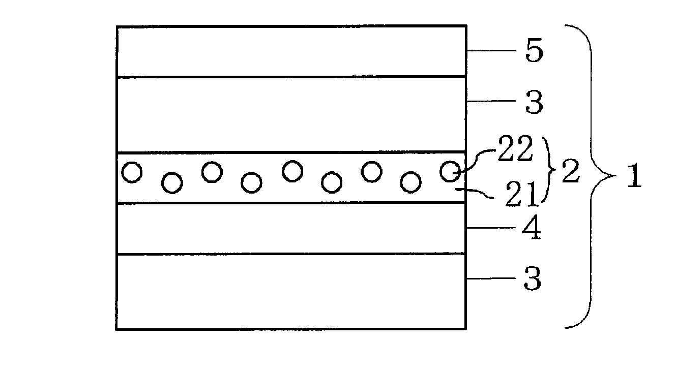
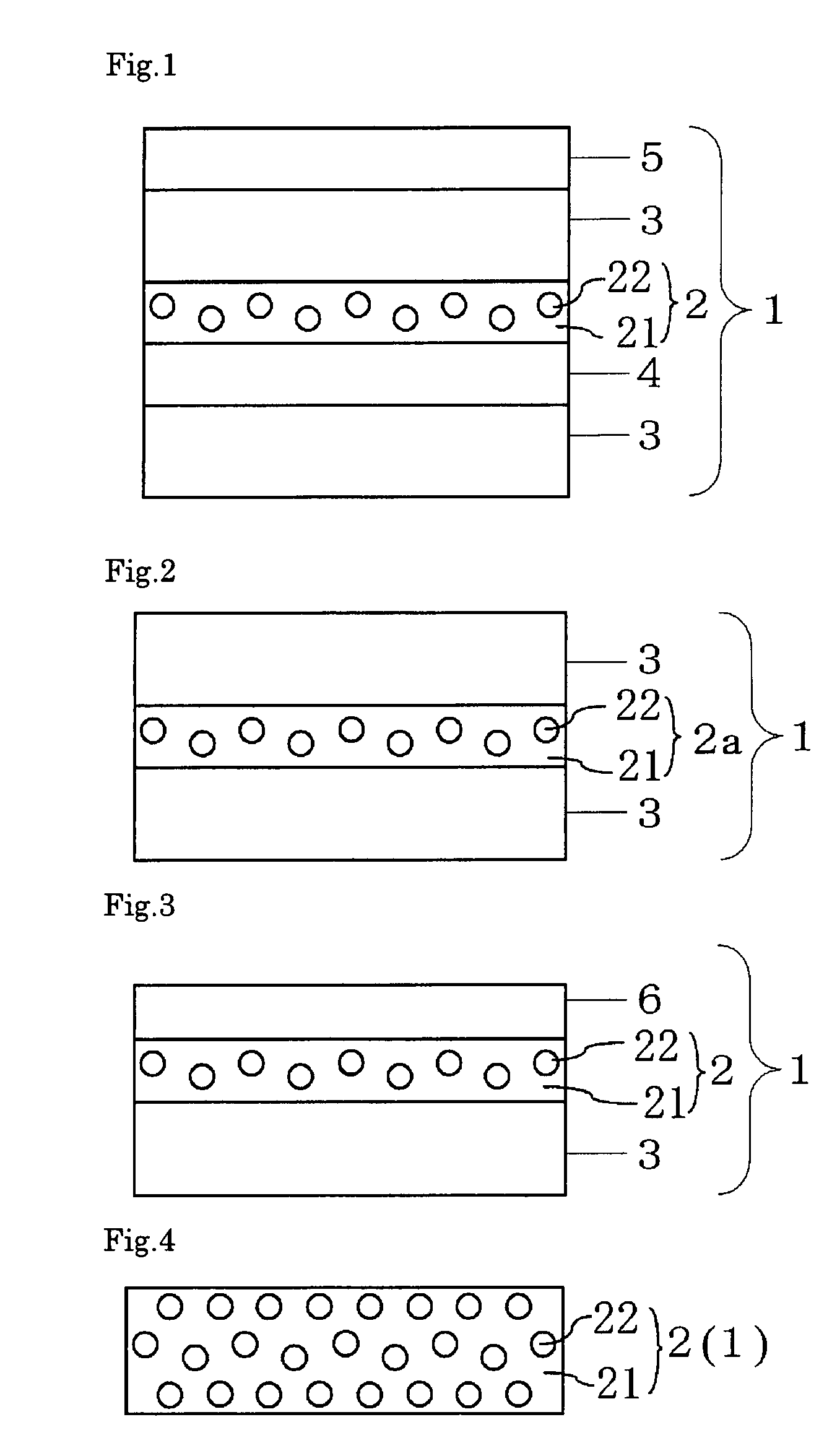
[0015]The transmission screen of the present invention is a transmission screen having a light diffusing layer comprising a transparent binder and light diffusing elements contained in the binder, wherein the light diffusing elements have a relative refractive index n of 0.75 or smaller or 1.25 or larger relative to refractive index of the transparent binder, both surfaces of the transmission screen are substantially smooth, and the screen has a total haze (JIS K7136:2000) of 10 to 85%. Hereafter, embodiments of the elements constituting the screen will be explained.

Problems solved by technology

However, these conventional transmission screens are expensive, and it is substantially impossible to see the other side of the screens, because they use polarization films or lens sheets.
However, such advertising representations are static, and unless sticking posters or giving painting again, the content of the advertisement does not change.
However, since conventional transmission screens are not transparent, it becomes impossible to see commercial advertising from the outside, and thus the show window becomes meaningless.
However, although the transmission screen of Japanese Patent Unexamined Publication No. 2001-242546 shows sufficient transparency, it does not have a sufficient viewing angle, and images cannot be clearly recognized from a direction deviated from the front direction.

Method used


Image

  • Transmission screen
  • Transmission screen
  • Transmission screen

Examples


example 1

[0059]On one surface of a polyethylene terephthalate film having a thickness of 100 μm (Lumirror T-60, Toray Industries, Inc.), a coating solution [a] for adhesive light diffusing layer having the following composition was applied and dried to form an adhesive light diffusing layer having a thickness of 40 μm. Then, the same polyethylene terephthalate film as that mentioned above was adhered on the adhesive light diffusing layer to obtain a transmission screen of Example 1. The refractive index of the transparent binder in the adhesive light diffusing layer was 1.50.

[0060]

Urethane type adhesive50parts(Takelac A-971, Takeda PharmaceuticalCo. Ltd., solid content: 50%)Isocyanate curing agent1.5parts(Takenate A-3, Takeda PharmaceuticalCo. Ltd., solid content: 75%)Hollow beads (HSC-110, Potters-Ballotini2partsCo., Ltd., refractive index ofgaseous portions: 1.0, mean diameterof gaseous portions: 5.5 μm)Ethyl acetate5partsToluene5parts

example 2

[0061]A transmission screen of Example 2 was obtained in the same manner as that of Example 1 except that the addition amount of the hollow beads in the coating solution [a] for adhesive light diffusing layer used in Example 1 was changed to 0.5 part, and the thickness of the adhesive light diffusing layer was changed to 20 μm.

example 3

[0062]A transmission screen of Example 3 was obtained in the same manner as that of Example 1 except that the addition amount of the hollow beads in the coating solution [a] for adhesive light diffusing layer used in Example 1 was changed to 8 parts, and the thickness of the adhesive light diffusing layer was changed to 45 μm.


PUM


Abstract

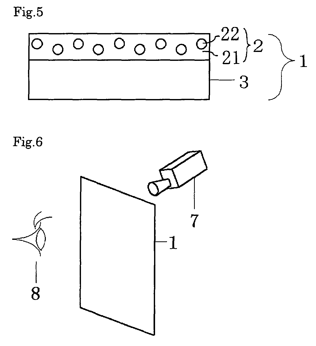
A transmission screen through which an observer can see the side of the screen opposite to the observer side, and which has a sufficient viewing angle is provided. The transmission screen is a transmission screen 1 having a light diffusing layer 2 comprising a transparent binder and light diffusing elements contained in the binder, and the transmission screen is constituted so that the light diffusing elements should have a relative refractive index n of 0.75 or smaller or 1.25 or larger relative to refractive index of the transparent binder, both surfaces of the transmission screen 1 should be substantially smooth, and the transmission screen should have a total haze (JIS K7136:2000) of 10 to 85%.

Description

BACKGROUND OF THE INVENTION[0001]1. Field of the Invention[0002]The present invention relates to a back projection type transmission screen, with which images projected from a projector can be recognized from the side of the screen opposite to the projector side. The present invention relates to a transmission screen utilizing a special light diffusing layer and thereby exhibiting a sufficient viewing angle and superior transparency, through which background can be seen (see-through property).[0003]2. Background Art[0004]Most of the conventionally and practically used transmission screens use polarization films, fresnel lens sheets, lenticular lens sheets and so forth in order to obtain high luminance and high contrast. However, these conventional transmission screens are expensive, and it is substantially impossible to see the other side of the screens, because they use polarization films or lens sheets.[0005]In show windows of stores, advertising representations are employed by st...

Claims


Application Information

Patent Timeline
Patent Type & Authority Patents(United States)
IPC IPC(8): G03B21/60G02B5/02G03B21/00G03B21/62
CPCG02B5/0242G02B5/0247G02B5/0278G03B21/10G03B21/62
Inventor HARADA, MASAHIROETORI, HIDEKINAKATA, HIROHIDE
Owner KIMOTO CO LTD
Why Eureka
Eureka Blog
Learn More