
Permeable ground levelling machine

A technology for leveling machine and ground, applied in the direction of roads, road repair, roads, etc., can solve the problems such as the inability to control the density of the permeable concrete mixture, the internal gap, the inability to ensure the completion of leveling, and the low construction accuracy.

Inactive Publication Date: 2018-11-06
薛峰
View PDF7 Cites 1 Cited by
  • Summary
  • Abstract
  • Description
  • Claims
  • Application Information

AI Technical Summary

Problems solved by technology

[0003] At present, in the construction process of roads, residential areas, parks, and factory floors, it is necessary to manually tamp the ground and pour the permeable concrete mixture with a certain viscosity and gap into the construction site through machinery, and then manually pour the permeable concrete mixture into the construction site. The material is spread out repeatedly to form a relatively flat surface, and then it is smoothed manually or mechanically. The above process cannot guarantee that the leveling can be completed within the bonding time of the adhesive; in addition, the labor intensity of the construction is high, the efficiency is low, and the water permeability cannot be guaranteed. Effect: when using mechanical troweling, due to the unevenness of the construction ground, it is impossible to control the density of the permeable concrete mixture and the internal gap of the permeable concrete mixture, which will easily lead to low construction accuracy and difficult to guarantee the construction quality

Method used


Image

  • Permeable ground levelling machine

Examples


Embodiment Construction

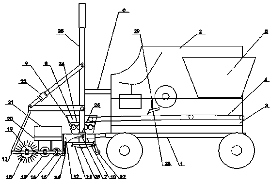
[0018] according to figure 1As shown, the present invention relates to a water-permeable ground leveling machine, which includes a tractor chassis 1 with road wheels, and the tractor chassis 1 is provided with a housing 2 with a V-shaped conveying channel 3, and the conveying channel A chute 29 is provided on the 3V-shaped side wall, and a hydraulic lifting plate 28 is installed in the chute 29, a power output device and a speed change device are installed in the housing 2, and a conveying device 4 is arranged in the conveying channel 3 A collection box 5 is installed at the rear end of the housing 2 and the discharge port of the collection box 5 corresponds to the rear end of the conveying device 4, and the front end of the tractor chassis 1 is provided with a suspension device 6, the Suspension device 6 is connected with a leveling working head 7, and described leveling working head 7 comprises material receiving box body 8, and the front end of described conveying device 4 ...


PUM


Abstract

The invention discloses a permeable ground levelling machine which comprises a traction vehicle chassis. A housing is arranged on the traction vehicle chassis, and a conveying device is arranged in the housing. A material collecting box and a suspension device are mounted at the rear end and the front end of the housing correspondingly. The suspension device is connected with a levelling work headwhich comprises a material collecting box body. The material collecting box body is provided with auger sets, and a vibrating screen is arranged below the auger sets. A hydraulic discharging baffle is arranged at the bottom of the material collecting box body, and telescopic oil cylinders are arranged at the two ends of the material collecting box body. Sensor receiving mounting racks are connected to the upper portions of the telescopic oil cylinders, bent plates bent forwards are mounted on the outer walls of the telescopic oil cylinders, and adjustable scraper blades are mounted at the other ends of the telescopic oil cylinders. A levelling rack is arranged between the bent plates and the sensor receiving mounting racks. A first flattening roller is arranged at the bottom of the rear end of the levelling rack, a thorn roller with a plurality of metal thorns is arranged at the bottom of the front end of the levelling rack, and a second flattening roller is arranged in the middle ofthe levelling rack. The above structure is adopted, and the permeable ground levelling machine has the advantages of being simple in structure, high in mechanization degree, high in efficiency, good in perspective effect, and capable of improving the construction precision, the construction quality and lowering the labor intensity.

Description

[0001] This application is a divisional application of the invention patent application with the application number: 2016105827344 and the name: "Water-permeable floor leveling machine". The original application date is: July 23, 2016. technical field [0002] The invention relates to a water-permeable concrete leveling device, in particular to a water-permeable ground leveling machine used on a laser leveling machine. Background technique [0003] At present, in the construction process of roads, residential areas, parks, and factory floors, it is necessary to manually tamp the ground and pour the permeable concrete mixture with a certain viscosity and gap into the construction site through machinery, and then manually pour the permeable concrete mixture into the construction site. The material is spread out repeatedly to form a relatively flat surface, and then it is smoothed manually or mechanically. The above process cannot guarantee that the leveling can be completed wit...

Claims


Application Information

Patent Timeline
Patent Type & Authority Applications(China)
IPC IPC(8): E04F21/24E01C19/48
CPCE01C19/4853E01C19/486E04F21/24
Inventor 薛峰
Owner 薛峰
Learn More