
Carbon fiber orthopaedic traction frame

An orthopedic traction frame and carbon fiber technology, applied in medical science, external fixator, vehicle rescue, etc., can solve the problems of difficult to reach the doctor's operation position, complicated operation, and the inability of the doctor to observe the operation situation, and achieve a stable structure Reliable, easy and fast operation, convenient opening and closing effect

Inactive Publication Date: 2018-11-30
玉林市好邦医疗设备有限责任公司
View PDF6 Cites 2 Cited by
  • Summary
  • Abstract
  • Description
  • Claims
  • Application Information

AI Technical Summary

Problems solved by technology

[0002] The traditional orthopedic traction frame is very complicated to operate, and it is difficult to achieve the surgical position that the doctor wants. The complicated operation has become a workload for the medical staff. The traditional orthopedic traction frame uses stainless steel or other metals as structural components. Imaging equipment (such as C-arm), because X-rays cannot penetrate these metal materials
In orthopedics, traction refers to a therapeutic operation or operation that uses a series of mechanical devices to straighten the fracture to maintain alignment and release pressure from other skeletal systems. This is one of the heaviest tasks for orthopedic surgeons. , now that people's medical level has improved, higher requirements have been put forward clinically, and more superior technical parameters are more in line with clinical use. The development of contemporary medicine, especially orthopedics and imaging surgery, is changing with each passing day. Many surgical and imaging technologies are inseparable from advanced The cooperation of medical equipment, the traditional orthopedic traction frame, uses stainless steel or other metals as structural components, imaging equipment (such as C-arm), because X-rays cannot pass through these metal materials, doctors cannot observe the operation

Method used


Image

  • Carbon fiber orthopaedic traction frame
  • Carbon fiber orthopaedic traction frame

Examples


Embodiment Construction

[0019] The specific embodiments of the present invention will be described in detail below in conjunction with the accompanying drawings, but it should be understood that the protection scope of the present invention is not limited by the specific embodiments.

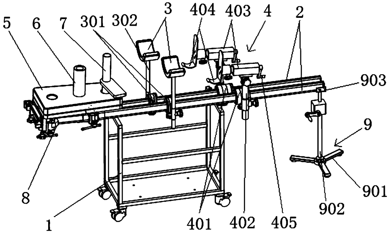
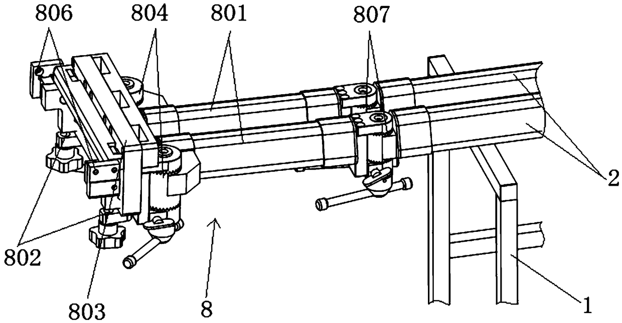
[0020] Embodiments of the present invention are as follows: Figure 1-2 As shown, a carbon fiber orthopedic traction frame includes a walking frame vehicle 1, which is made of a new type of carbon fiber composite material as a structural member. The walking frame vehicle 1 is supported with two guide rails 2, and the two guide rails 2 are located on the side of the walking frame vehicle 1. There are leg brackets 3 that can slide at the top, and the front ends of the two guide rails 2 are hinged with a docking assembly 8 that is connected to the operating bed. A perineal column 6 and a plaster support 7 are provided, the perineal column 6 can fix the sitting position of a person, the plaster support 7 is arranged on the...


PUM


Abstract

The invention discloses a carbon fiber orthopaedic traction frame comprising a traveling frame vehicle. Two guiding rails are arranged on the traveling frame vehicle in a supported mode; leg supportscapable of sliding are arranged on the positions, on the upper portion of the traveling frame vehicle, of the two guiding rails correspondingly; a butting assembly connected with an operation bed is hinged to the front ends of the two guiding rails in a transversely rotating mode; the butting assembly is provided with a hip seat plate; the hip seat plate is provided with a perineum column and a gypsum bracket; leg-foot traction mechanisms are arranged at the rear ends of the two guiding rails; and two lifting fixing frames capable of sliding are arranged on the lower portions of the rear endsof the two guiding rails. According to the carbon fiber orthopaedic traction frame, traction is convenient, movable steering can be achieved, the hip seat plate can be moved, leg rods are opened and closed conveniently through double cranksets and a two-section structure, and the structure is stable and reliable.

Description

technical field [0001] The invention relates to the technical field of orthopedic medical equipment, more specifically, it relates to a carbon fiber orthopedic traction frame. Background technique [0002] The traditional orthopedic traction frame is very complicated to operate, and it is difficult to achieve the surgical position that the doctor wants. The complicated operation has become a workload for the medical staff. The traditional orthopedic traction frame uses stainless steel or other metals as structural components. Imaging equipment (such as C-arms), because X-rays cannot penetrate these metal materials. In orthopedics, traction refers to a therapeutic operation or operation that uses a series of mechanical devices to straighten the fracture to maintain alignment and release pressure from other skeletal systems. This is one of the heaviest tasks for orthopedic surgeons. , now that people's medical level has improved, higher requirements have been put forward clin...

Claims


Application Information

Patent Timeline
Patent Type & Authority Applications(China)
IPC IPC(8): A61B17/66A61G13/12
CPCA61B17/66A61B2017/00831A61G13/1245A61G2210/10
Inventor 张建国文飞
Owner 玉林市好邦医疗设备有限责任公司
Learn More