
Collar having end-side teeth for a drivable wheel hub

a technology of end-side teeth and drivable wheels, which is applied in the field of colliers, can solve the problems of difficult process implementation with the necessary quality, high axial prestressing force, and disadvantageous effect of inner ring fixed seat, and achieve the effect of significantly increasing the load bearing par

Active Publication Date: 2010-12-28
SCHAEFFLER TECH AG & CO KG
View PDF16 Cites 32 Cited by
  • Summary
  • Abstract
  • Description
  • Claims
  • Application Information

AI Technical Summary

Benefits of technology

The invention provides a collar for a hub that has a design that avoids the disadvantages of previous collars. The collar has a thickened portion that is formed by plastically shaping the end piece of the hub. This thickened portion has a bead-shaped thickened portion that runs in a radial direction and is continuous or interrupted in the axial direction. The thickened portion can fill in the cavities for the teeth when the tooth is molded. The design of the collar allows for better filling of the teeth, increased loadbearing capacity, and improved performance. The thickened portion can have a different shape and size, and the edges of the teeth can be inclined at an angle. These features can be used to optimize the performance of the collar and reduce the impact of changes in the reference circle of the toothing.

Problems solved by technology

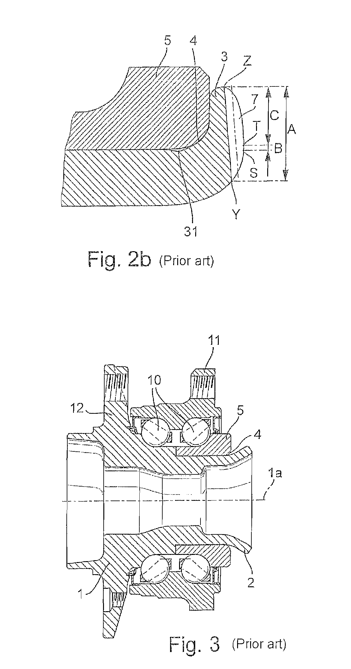
Also, a portion of the material under certain circumstances moves toward the inside in an uncontrolled way so that an annular gap 31 is formed between the inner ring 5 and the hub 1 and has a disadvantageous effect on the fixed seat of the inner ring 5.
However, the process is generally difficult to implement with the necessary quality owing to tolerances in the dimensions of the blank such as the wall thickness and diameter of the end piece.
The mounting of the articulated part with respect to the hub is easy owing to the self-centering but it requires a very high axial prestressing force.
The rigid configuration for transmitting high torques to the wheel can have a disadvantageous effect if, in the case of overloading, a fracture in the wheel hub leads to loss of the vehicle wheel in the most unfavorable case.

Method used


Image

  • Collar having end-side teeth for a drivable wheel hub
  • Collar having end-side teeth for a drivable wheel hub
  • Collar having end-side teeth for a drivable wheel hub

Examples


Embodiment Construction

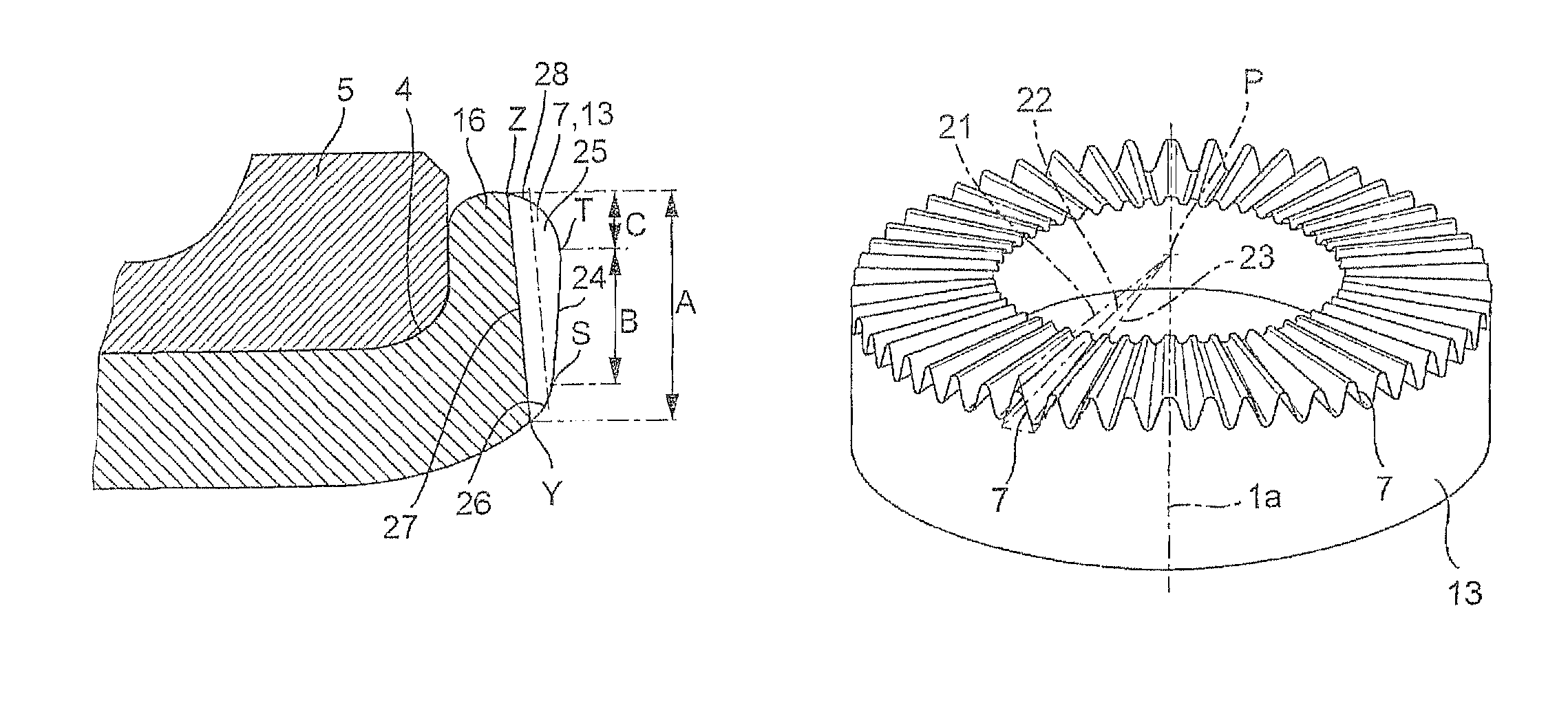
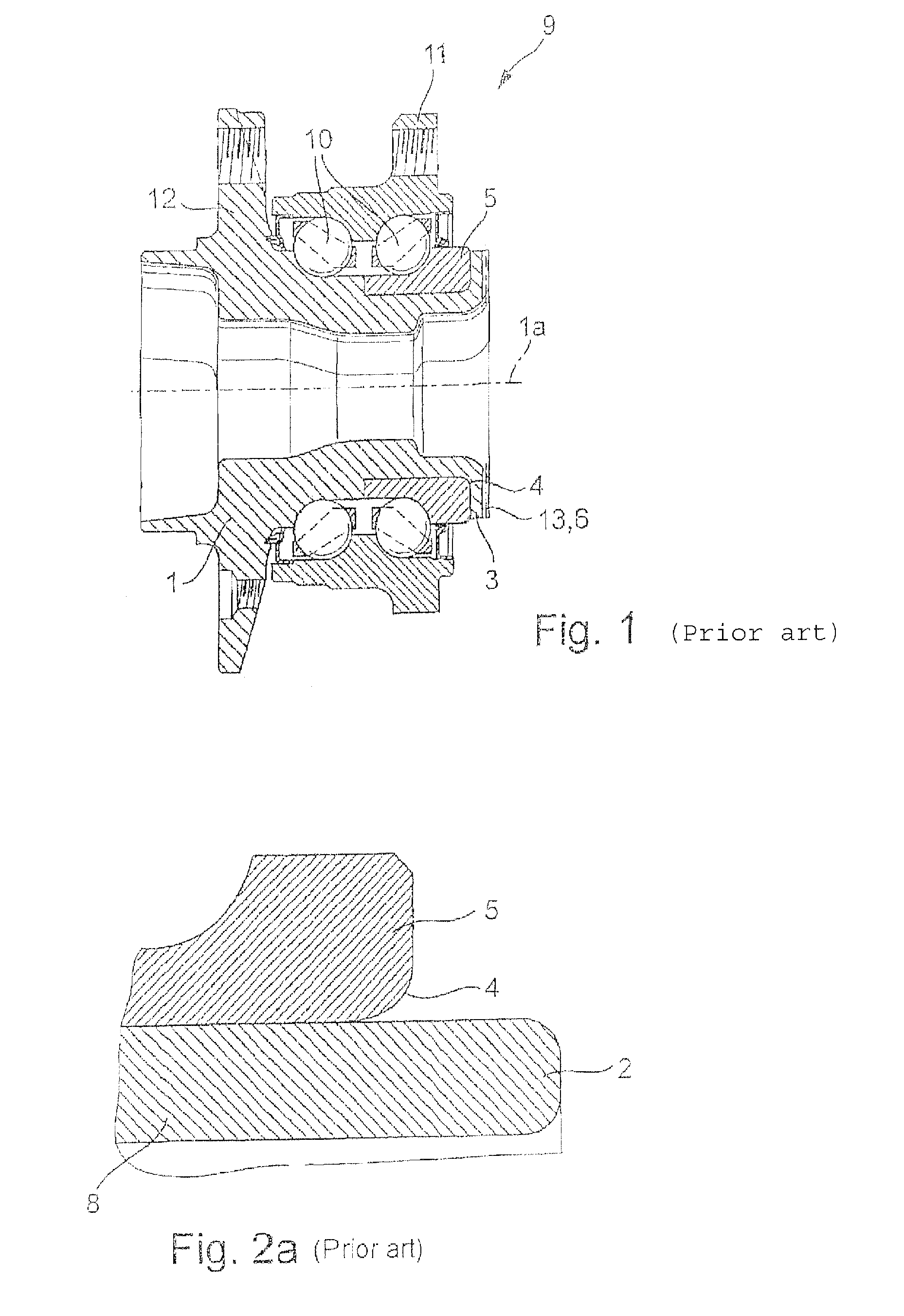
[0024]FIGS. 1 to 6 show longitudinal sections or details of longitudinal sections along the rotational axis 1a of a wheel bearing arrangement 9 in various modifications of exemplary embodiments of the invention. FIGS. 1, 3, 5 show a wheel bearing arrangement 9 with a hub 1, two rows of rolling bodies 10 and a vehicle flange 11. The hub 1 has a flange 12 for attaching a vehicle wheel (not illustrated) and is mounted by means of the rolling bodies 10 so as to be rotatable about the rotational axis 1a with respect to the vehicle flange 11 which is fixed to the vehicle. An inner ring 5 sits on the hub 1 and has a row of the rolling bodies 10 running on it. In the illustrations according to FIGS. 4 and 5, the end piece 14, 15 or 17 which is connected in one piece to the hub 1 is in the initial position before the rolling riveting. The inner ring 5 is, as illustrated in an enlarged detail according to FIG. 6b, held axially on the hub 1 by means of a collar 16 which has been made to protru...


PUM


Abstract

A collar, made from plastically deformed material, of a hub. The collar holds at least one inner ring of a wheel bearing unit on the hub in an axially fixed manner. Also, end-side teeth, are formed in the collar for engaging in a mating toothing.

Description

FIELD OF THE INVENTION[0001]The invention relates to a collar made from cold plastically shaped material of a hub, with which at least one inner ring of a wheel bearing unit is secured axially in a fixed manner on the hub and in which teeth for engagement in a mating toothing are formed at the end.BACKGROUND OF THE INVENTION[0002]DE 36 36 243 A1 is concerned with such a collar. The wheel bearing unit, generally an angular ball bearing arrangement or angular roller arrangement, is held free of play in a prestressed fashion by means of the collar. The finished collar 3 according to FIG. 1 is, as illustrated in FIG. 2a and FIG. 3, shaped from a hollow end piece 2 which is formed in one piece with a hub 1. When the collar 3 is formed, the material of the end piece 2 is turned-over plastically over the edge 4 of the inner ring 5 radially toward the outside. If the collar 3, as also illustrated in FIG. 2b, has an end toothing 6 with teeth 7 for engagement in a mating toothing (not illustr...

Claims


Application Information

Patent Timeline
Patent Type & Authority Patents(United States)
IPC IPC(8): F16C13/00F16C35/00F16H55/10
CPCB60B27/0005B60B27/0031B60B27/0084B60B27/0094F16C43/04F16D1/072F16D1/076F16C19/186Y10T74/1987F16C2326/02F16C19/18F16C35/063B60B27/00
Inventor LANGER, ROLANDMASUR, ERNSTHEISS, RALFFUELLER, BENNONIEBLING, PETER
Owner SCHAEFFLER TECH AG & CO KG
Learn More