Mechanically locked blind bolt fastener

a technology of mechanical locking and fasteners, which is applied in the direction of fastening means, screws, load-modifying fasteners, etc., can solve the problems of affecting the installation of fasteners, and unable to access the blind sid

Active Publication Date: 2010-12-28
PRATT JOHN D
View PDF37 Cites 24 Cited by
  • Summary
  • Abstract
  • Description
  • Claims
  • Application Information

AI Technical Summary

Benefits of technology

[0015]The present invention advantageously provides a blind bolt fastener having a core bolt to body mechanical lock and a sleeve to body mechanical lock. The core bolt is threadingly engaged with the sleeve. The body is positioned between a wrenching region of the core bolt and the sleeve. The core bolt has a groove for receiving a nose portion of the body to mechanically lock the core bolt to the body. The sleeve has a protrusion (or nose region) for engaging a groove in the body to mechanically lock the sleeve to the body. In a preferred embodiment, the core bolt mechanically locks to an integrally formed body and sleeve to prevent the core bolt from unthreading from the sleeve and / or the body.

Problems solved by technology

Often, however, access to the blind side is not possible, which can complicate fastener installation.
Conversely, positioning the break groove to break flush to below the head surface can result in cavities that must be filled.
In addition, low breaks (below flush) may result in some loss of strength in the fastener head.
Both of these approaches, however, require additional steps in the process of installing the fasteners into the aircraft and / or require additional components to be included with the fasteners.
Further, it is not economically feasible to incorporate a locking ring into a high strength blind fastener; particularly the threaded type described herein.
Otherwise, the fasteners will fail before the panels fail.
Composites, however, cannot endure the high compressive stresses induced by the installation of conventional fasteners designed for metallic structure.
Existing blind fasteners incorporating a locking ring fail to provide one or more of the above-mentioned features.
This softening of the sleeve necessarily extends into the shear plane, reducing joint strength and / or stiffness.
In addition, the pull-type nature of these fasteners causes a majority of the installation clamp load to relax upon the fracture of the pintail during installation.
Specifically, the pintail of the pull-type fasteners tends to recoil upon fracture of the pintail.
Existing blind rivets induce minute clamp load or sheet gathering capability and have an extremely small blind side upset compared to blind bolts.
These are generally suitable for low-strength applications in secondary metal structure (e.g., control surfaces), but are not strong enough for highly loaded primary structure (e.g., fuselage and wing joints).

Method used


Image

  • Mechanically locked blind bolt fastener
  • Mechanically locked blind bolt fastener
  • Mechanically locked blind bolt fastener

Examples


Embodiment Construction

[0027]While the present invention is described with reference to the embodiments described herein, it should be clear that the present invention should not be limited to such embodiments. Therefore, the description of the embodiments herein is illustrative of the present invention and should not limit the scope of the invention as claimed.

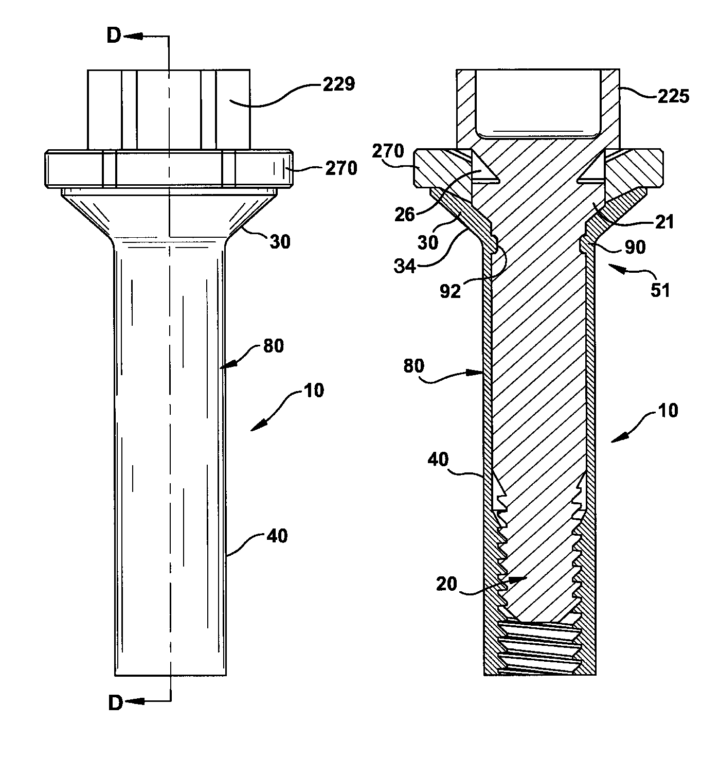
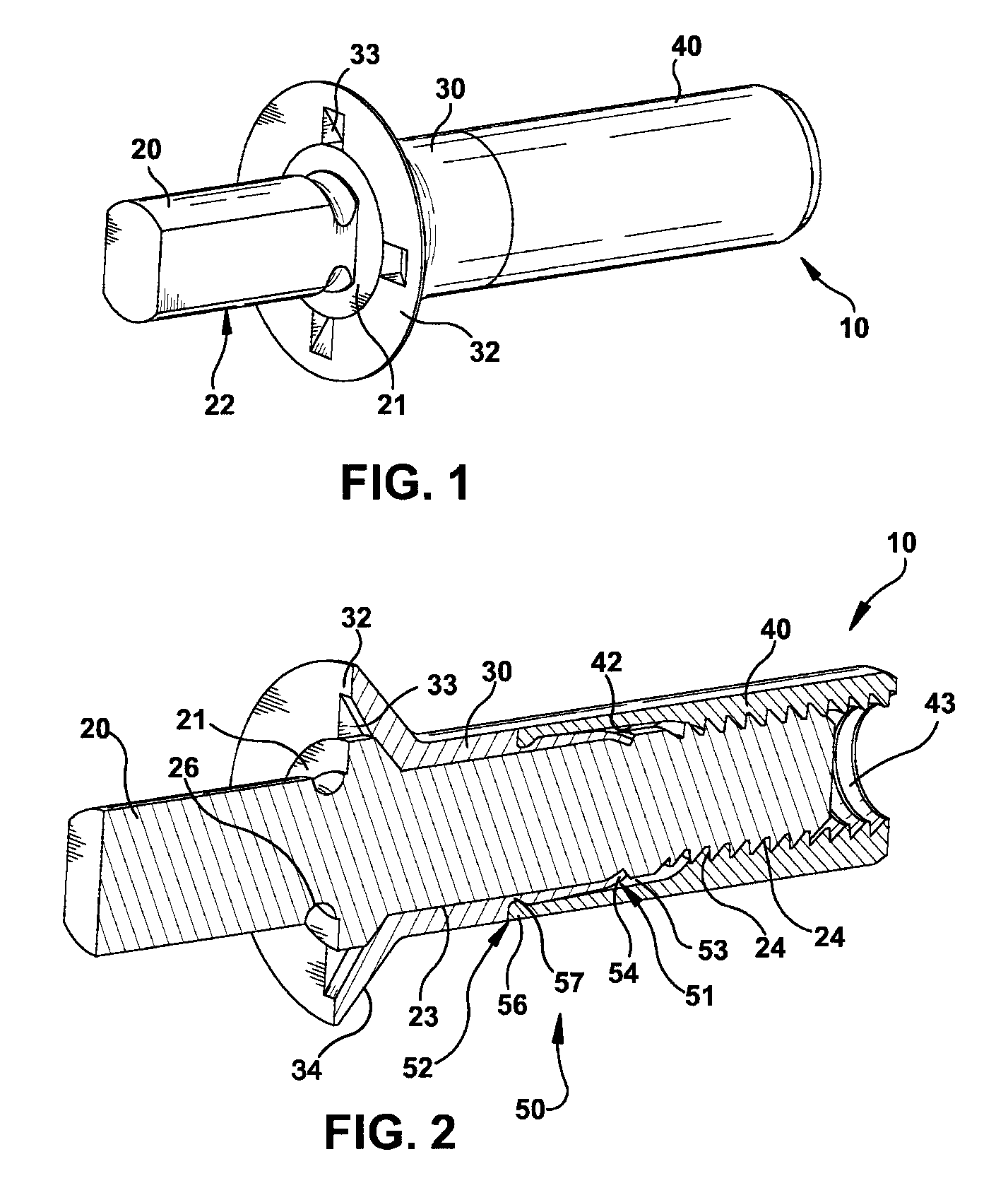
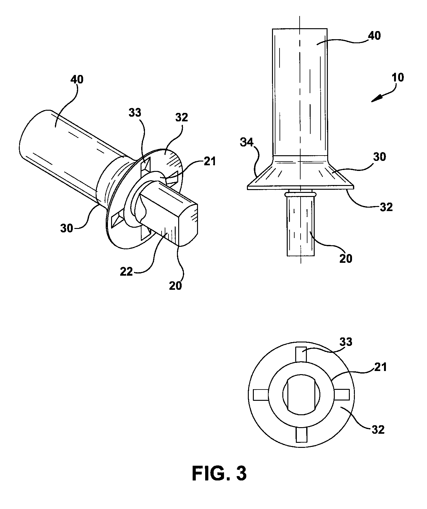
[0028]Reference will now be made in detail to the embodiments of the invention as illustrated in the accompanying figures. FIGS. 1-4 illustrate an embodiment of the present invention having a mechanically locked blind bolt fastener 10. The mechanically locked blind bolt fastener 10 comprises a core bolt 20, a body 30, a deformable sleeve 40, and at least one mechanical lock 50. The core bolt 20 is threadingly engaged with the deformable sleeve 40 and rotatively engaged with the body 30. The body 30 may be integrally formed with the deformable sleeve 40 into a single deformable body, or alternatively, the body 30 may be separate from the deformable ...


PUM


Abstract

The present invention provides a blind bolt fastener having a core bolt. The core bolt has a threaded portion and a non-threaded portion engaging a deformable sleeve and a body. A protrusion extends from the sleeve or the body to engage a groove in the core bolt to prevent axial movement of the core bolt with respect to the body and the sleeve. An optional drive nut is positioned between a head of the body and wrenching flats of the core bolt. The drive nut has protrusions engaging mating members in the head of the body.

Description

CROSS-REFERENCE TO RELATED APPLICATIONS[0001]This application claims priority from U.S. Provisional Patent Application No. 60 / 777,379, entitled “Mechanically Locked Blind Bolt Fastener” filed on Feb. 28, 2006, which is hereby incorporated by reference.FIELD OF THE INVENTION[0002]The present invention is generally related to blind fasteners, and more particularly to mechanically locked blind bolt fasteners.BACKGROUND OF THE INVENTION[0003]Blind fasteners are used in a variety of applications to connect two or more workpieces together. In the construction of aerodynamic designs, such as control surfaces on aircraft and the like, a substantially flush surface usually is desired on the accessible side of the panels. Often, however, access to the blind side is not possible, which can complicate fastener installation. In these cases, the use of a blind fastener is appropriate, since access to only one side of the panel is available to install the fastener.[0004]Typical blind fasteners com...

Claims


Application Information

Patent Timeline
Patent Type & Authority Patents(United States)
IPC IPC(8): F16B13/04
CPCF16B19/1054F16B31/021F16B29/00F16B19/1072
Inventor PRATT, JOHN D.
Owner PRATT JOHN D
Why Eureka
Try Eureka