Electrical connector

a technology of electrical connectors and connectors, applied in the direction of electrical apparatus, connection, coupling device connection, etc., can solve the problems of increasing manufacturing costs and complex operation, and achieve the effect of saving costs and simplifying the structure of connectors

Inactive Publication Date: 2010-12-28
HON HAI PRECISION IND CO LTD
View PDF4 Cites 3 Cited by
  • Summary
  • Abstract
  • Description
  • Claims
  • Application Information

AI Technical Summary

Benefits of technology

[0007]An object of the invention is to provide a connector, which is capable of simplifying the structure of the connector and saving the cost.
[0009]Comparing with the traditional connector, the connector according with the present invention fastens the chip via the inflexed press portion of a pair of levers, which simplifies the structure of the connector and economizes the cost of manufacture and is efficient for operating.

Problems solved by technology

However, said connector needs both a lever and a cover to engage with each other to retain the chip, it has so many elements that will increase the cost of manufacture and is complex for operating.

Method used


Image

  • Electrical connector
  • Electrical connector
  • Electrical connector

Examples


Embodiment Construction

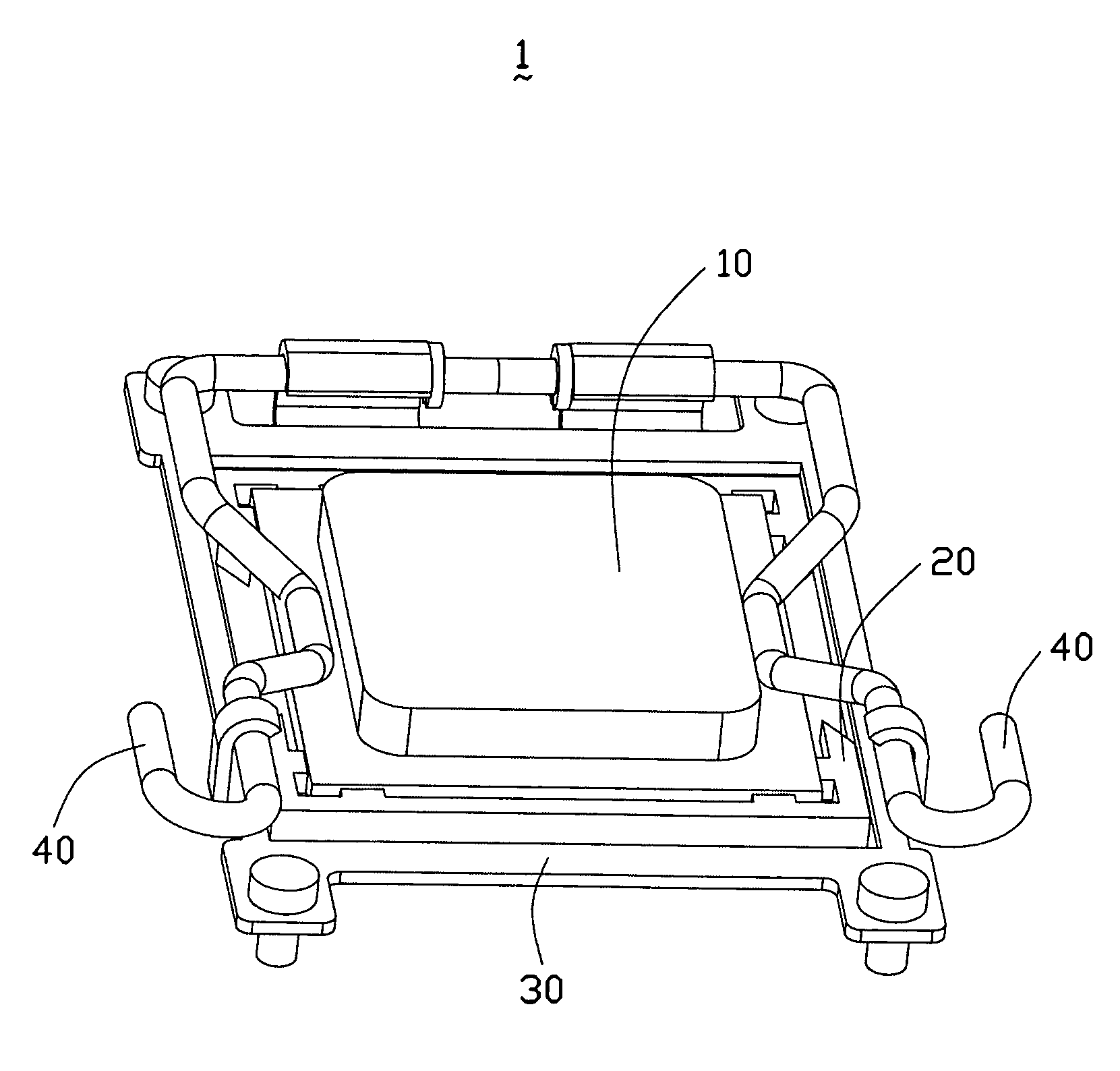
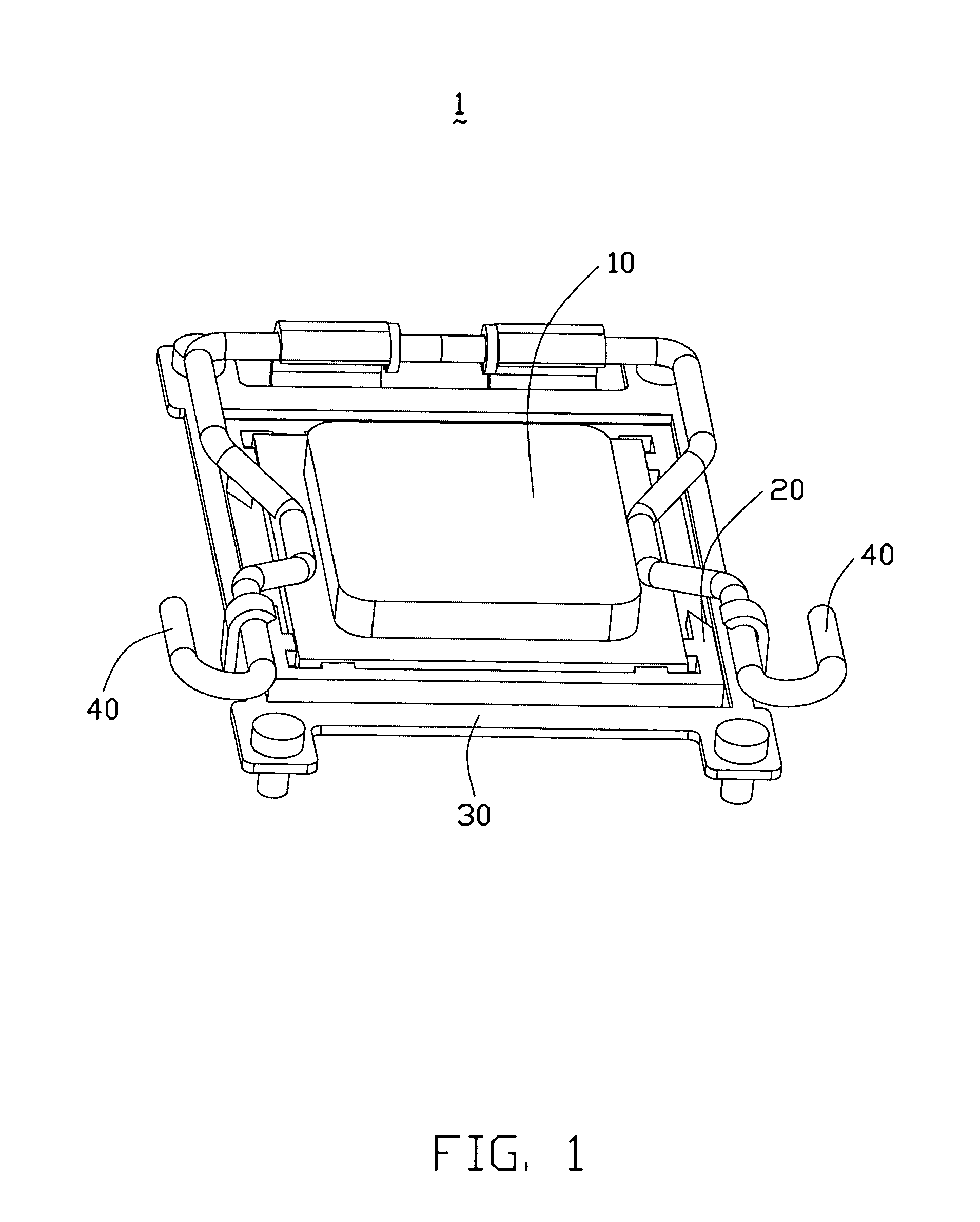
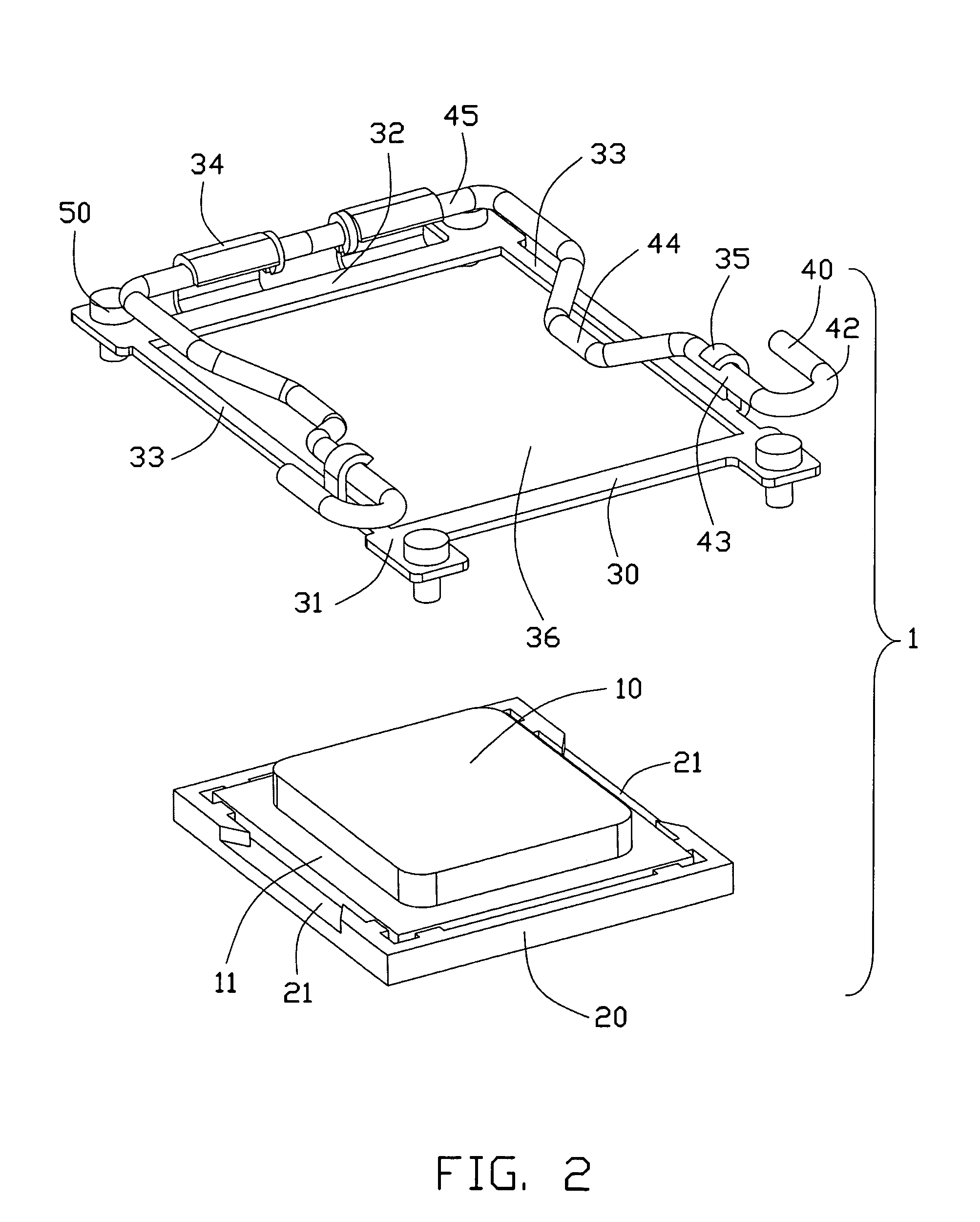
[0014]Referring to FIGS. 1 to 3, the FIGS. Show one preferred embodiment of a connector 1 according with the present invention. The connector 1 includes an insulating housing 20 for receiving a CPU chip 10 and a bracket 30 encircling the insulating housing 20. On the bracket 30, there mounted a pair of levers 40. When the lever 40 is on an opening condition, the chip 10 can be picked up from the connector 1, and when the lever 40 is on a close condition, the chip 10 is fastened in the insulating housing 20.

[0015]Please referring to FIG. 1 to FIG. 3, the insulating housing 20 is approximate a rectangular shape with a receiving slot (not labeled) defined thereon. In the bottom of the receiving slot, there defines a plurality of terminals (not shown) for connecting with the chip 10. The chip 10 is generally constructed with the central protruding from the base, thereby the left construction of the base forms a plurality of contact surfaces 11.

[0016]Said bracket 30 is mounted surroundin...


PUM


Abstract

An electrical connector comprises an insulating housing, a pair of levers and a bracket. The insulating housing includes a receiving slot for receiving a chip. The bracket encircles the insulating housing, which includes several side walls and a empty portion surrounded by the side walls, on the side wall there defines a fasten portion. The lever is set beside two opposite side of the chip, which comprises a pintle portion, an operating portion and a main portion connecting the pintle portion and the operating portion, the pintle portion is received in the fasten portion of the bracket. Protruding towards inner side from the main portion there forms a press portion for retain the chip. The structure of the invention is simply, which economizes the cost of manufacture and is efficient for operating.

Description

BACKGROUND OF THE INVENTION[0001]1. Field of the Invention[0002]The present invention relates to the art of electrical connector, and more particularly to an electrical connector utilizing a lever to retain a CPU chip.[0003]2. Description of the Related Art[0004]As is well known to those skilled in computer art, when electrically connecting a CPU chip to an electrical connector, there must be some device to provide a positive force on the chip, not only to retain the chip from dropping off the connector but also to promise the chip electrically connecting with the contact of the connector tightly and stably to ensure a good electrical performance therebetween. The American patent with an issue number U.S. Pat. No. 6,485,320 discloses an electrical connector, which includes a base for receiving a CPU chip, a moveable cover and lever mounted on the base, via the lever engaging with the cover to retain the chip, thereby to realize an electrical connecting between the contact of the con...

Claims


Application Information

Patent Timeline
Patent Type & Authority Patents(United States)
IPC IPC(8): H01R13/625
CPCH05K7/1053
Inventor FAN, CHIA-WEI
Owner HON HAI PRECISION IND CO LTD
Why Eureka
Try Eureka