Rotary cutting deck with hydraulic direct driven spindle

a technology of hydraulic drive and cutting deck, which is applied in the field of rotary cutting decks, can solve the problems of hydraulic direct drive spindles, presenting a risk to operators and bystanders, and rotary cutting decks having hydraulic direct driven spindles, so as to reduce the likelihood of driving the blade, reduce the risk of blade detachment, and significantly reduce the risk of blade damage to the spindle or hydraulic motor

Active Publication Date: 2011-01-04
DEERE & CO
View PDF26 Cites 15 Cited by
  • Summary
  • Abstract
  • Description
  • Claims
  • Application Information

AI Technical Summary

Benefits of technology

[0007]The rotary cutting deck with a hydraulic direct driven spindle can reduce the likelihood of driving the blade at high rotational speeds if it starts to become loose, and reduce the risk of blade detachment at high rotational speeds. The invention allows the blade to slip if it strikes a stationary object, significantly reducing the risk of damage to the blade, spindle or hydraulic motor, and reducing the possibility of one or more components failing.

Problems solved by technology

A first problem with conventional rotary cutting decks having hydraulic direct driven spindles occurs if the captured blade starts to become loose.
This presents a risk to operators and bystanders.
A second problem with conventional rotary cutting decks having hydraulic direct driven spindles occurs if the blade strikes a stationary object such as a large rock or stump.
If this occurs, the blade, spindle or hydraulic motor may become damaged or fracture from direct axial loads.

Method used


Image

  • Rotary cutting deck with hydraulic direct driven spindle
  • Rotary cutting deck with hydraulic direct driven spindle
  • Rotary cutting deck with hydraulic direct driven spindle

Examples


Embodiment Construction

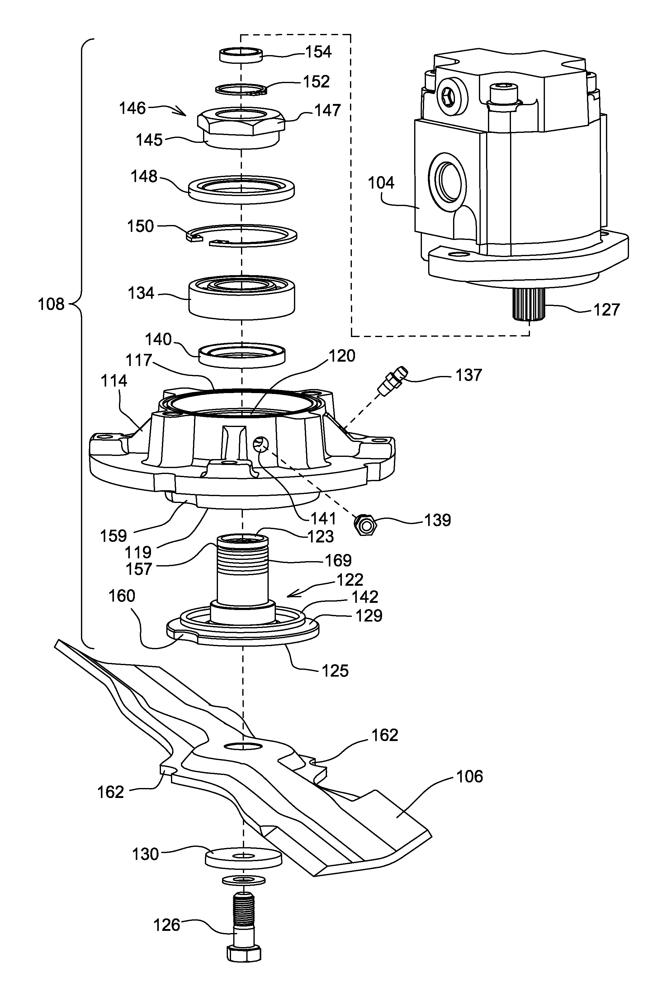
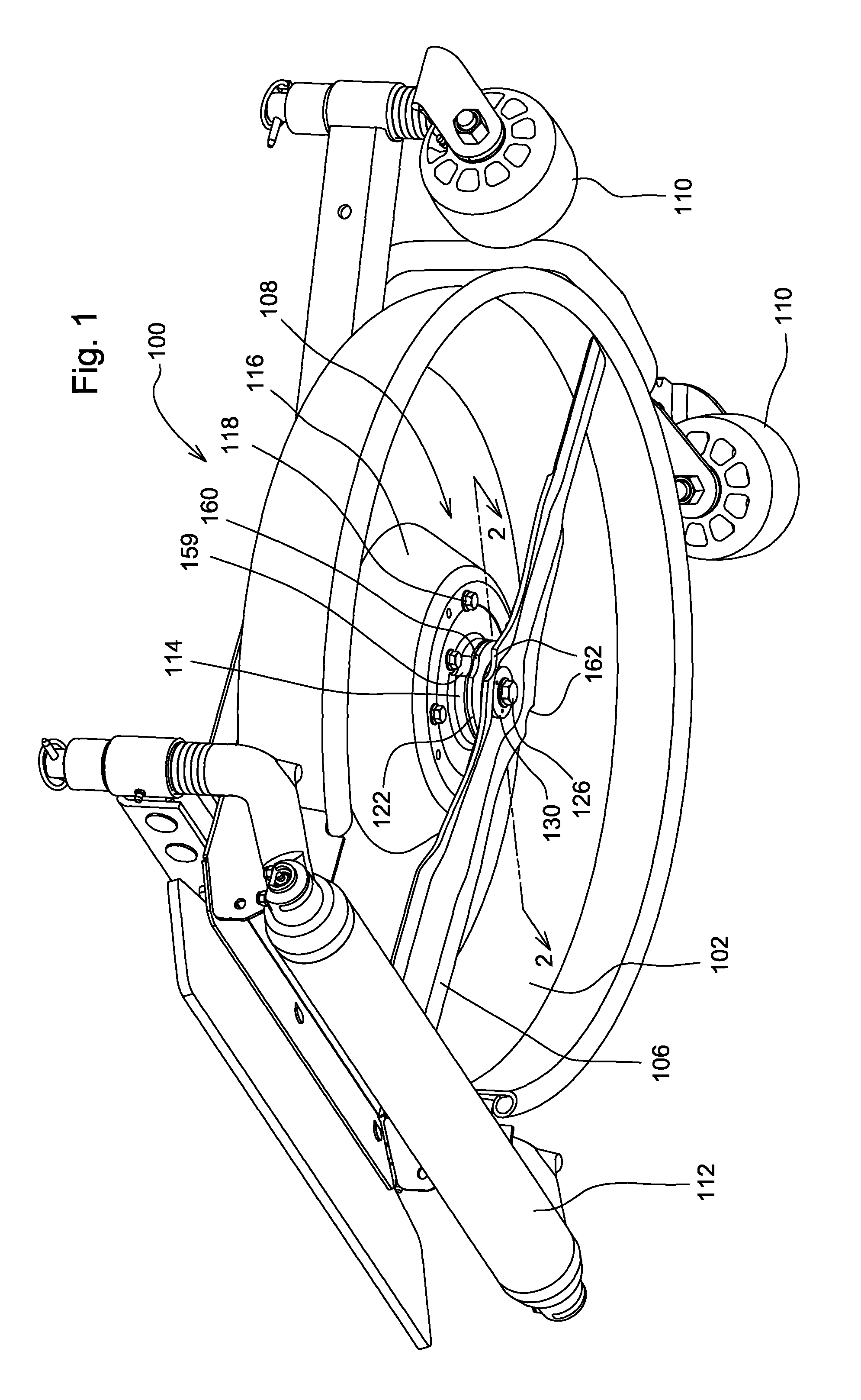
[0011]As shown in FIGS. 1-3, in a first embodiment, rotary cutting deck 100 may be carried by a traction vehicle. Typically, three or more rotary cutting decks are carried by the same traction vehicle. Each rotary cutting deck may include a circular inverted dish-shaped cutting chamber 102. Hydraulic motor 104 may be mounted to the upper top surface of the rotary cutting deck, and the motor may be connected by hydraulic conduits to a hydraulic pump. The hydraulic motor rotates cutting blade 106 that is removably mounted to the lower end of hydraulic direct driven spindle 108 under the deck. The rotary cutting deck may be supported to move over the ground surface by a front pair of rollers 110, casters or wheels, and a rear roller 112.

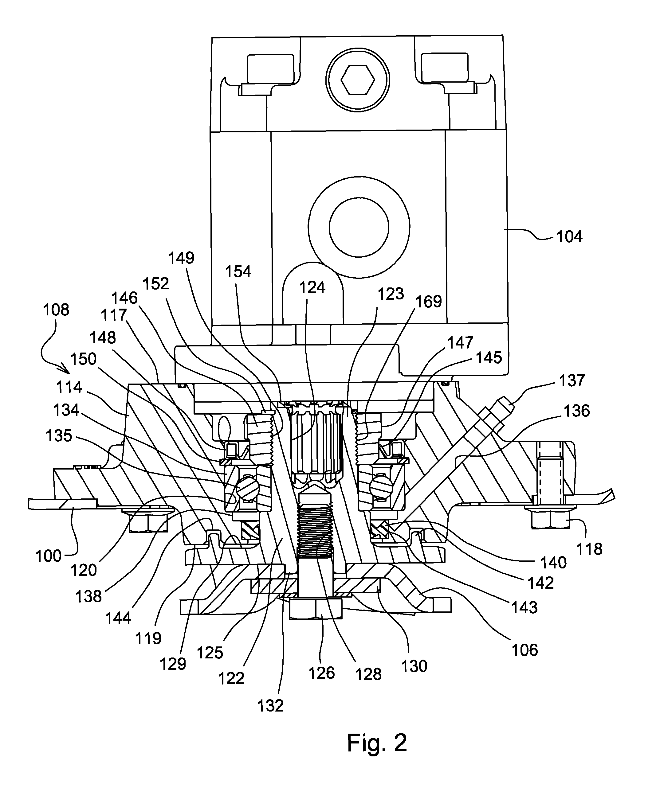
[0012]In one embodiment, hydraulic direct driven spindle 108 may include spindle housing 114 mounted to the rotary cutting deck, blade adapter 122 that rotates within the housing and connects rotary cutting blade 106 to hydraulic motor 104, annular bear...


PUM


Abstract

A rotary cutting deck with a hydraulic direct driven spindle includes a spindle housing attached to the rotary cutting deck and having a stepped internal bore, and a blade adapter inserted into the stepped internal bore and having a first, upper end connected to a hydraulic motor, and a second lower end with a contact surface against which a rotary cutting blade is clamped. A bolt threaded to the blade adapter provides the only clamping force between the rotary cutting blade and the contact surface, which is substantially flat and does not capture the blade. A notch or hole in the outer edge of the hydraulic direct driven spindle may be engaged to hold the hydraulic direct driven spindle stationary relative to the blade during installation or detachment of the blade.

Description

FIELD OF THE INVENTION[0001]The present invention relates to a rotary cutting deck with a cutting blade mounted to a hydraulic motor, and specifically to a rotary cutting deck with a hydraulic direct driven spindle.BACKGROUND OF THE INVENTION[0002]Many new and existing golf courses have narrowed their fairways and expanded their rough areas on either side of the fairways. Roughs require less care than fairways, so narrowing the fairways allows golf course operators to lower their maintenance costs. For example, irrigation requirements may be reduced if only the fairways are watered. If grasses in the roughs are allowed to grow longer, those non-irrigated areas are less brown. Trees and other aesthetic features may be located in the roughs, because roots and shade can inhibit turf growth in the fairways.[0003]However, golf course roughs still must be maintained regularly using grass mowing machines that can mow the vegetation at an acceptable length and appearance. Equipment for mowi...

Claims


Application Information

Patent Timeline
Patent Type & Authority Patents(United States)
IPC IPC(8): A01D34/00
CPCA01D34/6806A01D75/182A01D75/18A01D34/733
Inventor CAMPBELL, CHAD W.
Owner DEERE & CO
Why Eureka
Try Eureka