Retractable screen and frame assembly

a frame and screen technology, applied in the direction of shutters/movable grilles, door/window protection devices, insect protection, etc., can solve the problems of screen slipping out of the frame, screen binding, and high cost of application of these types of coatings

Inactive Publication Date: 2011-01-04
QUANEX HOMESHIELD LLC
View PDF23 Cites 24 Cited by
  • Summary
  • Abstract
  • Description
  • Claims
  • Application Information

AI Technical Summary

Benefits of technology

[0007]The present invention is a retractable screen and frame assembly. The assembly includes a first pair of spaced frame members and a second pair of spaced frame members extending between the first pair of frame members to define an opening. A first track is disposed along one of the frame members of the first pair and a second track is disposed along the other one of the frame members of the first pair. A canister extends across the opening and between the first pair of frame members. A screen cloth extends between a trailing edge, supported by the canister, and a leading edge for dispensing the screen cloth from the canister to cover the opening and for retracting the screen cloth within the canister to uncover the opening. A control bar extends across the opening between a first end and a second end. The leading edge of the screen cloth is attached to the control bar between the ends thereof for guiding the leading edge of the screen cloth back and forth over the opening to cover and uncover the opening. A first glide is movably supported by the first end of the control bar for sliding along the first track. A second glide is movably supported by the second end of the control bar for sliding along the second track. A biasing device reacts between the first end of the control bar and the first glide for biasing the first glide against the first track. This biasing allows relative movement between the first end and the first glide when sliding the first glide along the first track. Therefore, the biasing device compensates for varying distances between the first track and the second track.
[0008]By placing a biasing device between the first glide and the first end of the control bar, the biasing device automatically biases the control bar axially with respect to the tracks. Therefore, the biasing device biases the control bar toward and away from the tracks. Additionally, the biasing provided by the biasing device is not dependent upon the use of friction reducing materials and processes for the glides, the tracks, and the control bar. Therefore, the biasing provided by the biasing device allows the control bar and the glides to smoothly slide along the first and the second tracks without binding even when the first and the second tracks are out of parallel with respect to each other. Similarly, if the first track and / or the second track are “bowed”, the biasing provided by the biasing device also allows the control bar to glide smoothly across the tracks without binding.

Problems solved by technology

However, with this type of assembly, the screen has the tendency to bind as it is rolled along the tracks.
Additionally, the wheels on the surround tend to come off of the tracks, causing the screen to fall out of the frame.
However, application of these types of coatings is expensive due to the materials, time, and steps added to the assembly process.
The use of the special materials and / or special processing steps adds time and cost to the manufacture of the sliding screen assembly.

Method used


Image

  • Retractable screen and frame assembly
  • Retractable screen and frame assembly
  • Retractable screen and frame assembly

Examples


Embodiment Construction

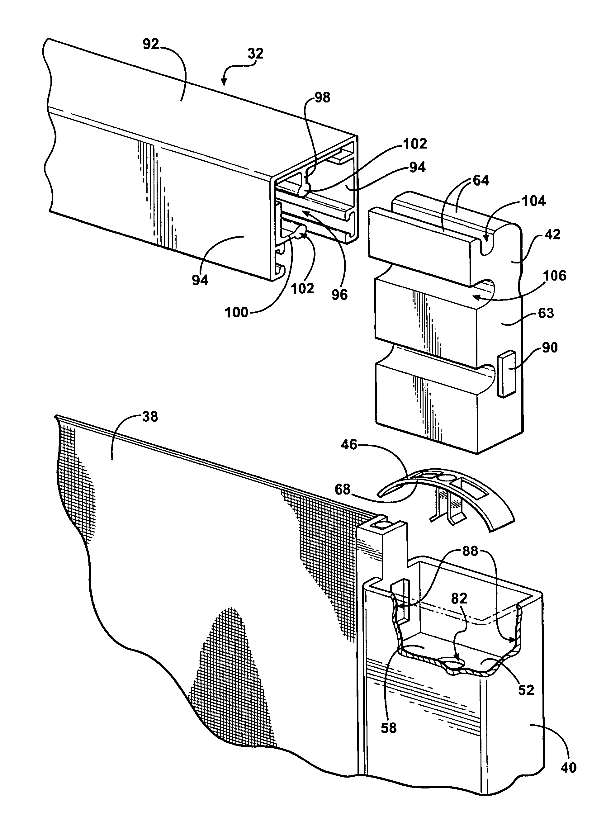
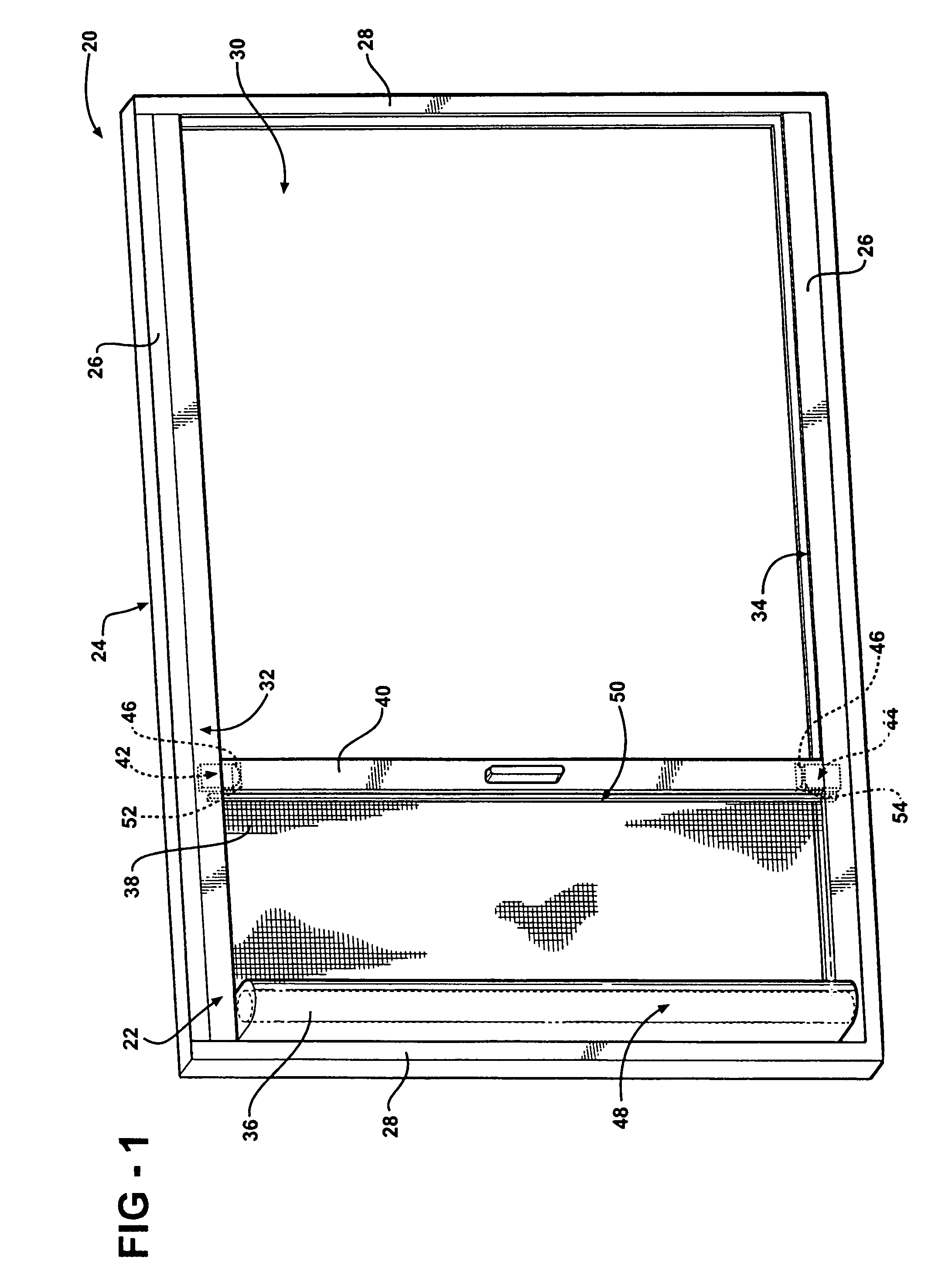
[0020]The present invention is a retractable screen and frame assembly for placement into an aperture for a window or a door. The assembly is shown generally at 20 in FIG. 1 and includes a retractable screen 22 and a frame 24.

[0021]Referring to FIG. 1, the frame 24 is disposed into the aperture and the retractable screen 22 is assembled to the frame 24. The frame 24 includes a first pair of spaced frame members 26 and a second pair of spaced frame members 28 extending between the first pair of frame members 26 to define an opening 30. Generally, the first pair of spaced frame members 26 are horizontal and the second pair of spaced frame members 28 are vertical to define a square or rectangular shaped opening 30. However, the frame members 26, 28 are not limited to this orientation and may be disposed at any desired orientation. A first track 32 is disposed along one of the frame members 26 of the first pair. A second track 34 is disposed along the other one of the frame members 26 o...


PUM


Abstract

The present invention is a retractable screen (22) and frame (24) assembly (20). The frame (24) includes a first track (32) and a second track (34) in spaced and parallel relationship to the first track (32). The retractable screen (22) includes a canister (36), a screen cloth (38), a control bar (40), a first glide (42), a second glide (44), and a biasing device (46). The biasing device (46) is disposed between a first end (52) of the control bar (40) and the first glide (42). The first glide (42) is inserted into the first track (32) and the second glide (44) is inserted into the second track (34). The glides (42, 44) slide along the respective tracks (32, 34) while the biasing device (46) biases the first end (52) of the control bar (40) with respect to the first track (32). The biasing provided by the biasing device (46) prevents the control bar (40) from binding with the tracks (32, 34) as the control bar (40) and the glides (42, 44) are slid along the tracks (32, 34).

Description

BACKGROUND OF THE INVENTION[0001]1. Field of the Invention[0002]The invention generally relates to a retractable screen and frame assembly for covering and uncovering a door or a window opening.[0003]2. Description of the Related Art[0004]Traditional door or window openings are covered and uncovered with a screen and frame assembly that rolls. The opening is bounded by a frame and the assembly includes a pair of opposing tracks that are adjacent the frame in spaced and parallel relationship. The screen includes a surround having four sides and wheels on two opposing sides of the surround that correspond to the opposing tracks. When the screen is installed to the tracks inside the opening, the wheels allow the screen to roll along the tracks across the opening. However, with this type of assembly, the screen has the tendency to bind as it is rolled along the tracks. Additionally, the wheels on the surround tend to come off of the tracks, causing the screen to fall out of the frame.[0...

Claims


Application Information

Patent Timeline
Patent Type & Authority Patents(United States)
IPC IPC(8): A47G5/02
CPCE06B9/54E06B2009/543
Inventor MARTINEAU, ROBERT C.SAWYERS, JEFFREY V.
Owner QUANEX HOMESHIELD LLC
Why Eureka
Try Eureka