Electrical connector

a technology of electrical connectors and connectors, applied in the direction of electrical discharge lamps, securing/insulating coupling contact members, coupling device connections, etc., to achieve the effect of superior vibration resistan

Active Publication Date: 2011-01-04
DDK LTD
View PDF10 Cites 24 Cited by
  • Summary
  • Abstract
  • Description
  • Claims
  • Application Information

AI Technical Summary

Benefits of technology

[0016]The invention has been achieved in view of these problems with the prior art described above, and the invention has an object to provide an electrical connector which is superior in resistance to vibration and enables space-saving and floating of part.
[0022](1) An electrical connector claimed in claim 1 is the electrical connector 10 consisting of a plug connector 50 and a receptacle connector 20 detachably fitted with each other, said receptacle connector 20 including a plurality of receptacle contacts 24 each having a first contact portion 26 adapted to contact a mating contact, a first fixed portion 28 to be fixed to a block 22, and a first connection portion 30 to be connected to a substrate 90, and the block 22 for arranging and holding said receptacle contacts 24, and said plug connector 50 including a plurality of plug contacts 56 each having a second contact portion 58 adapted to contact said receptacle contact 24, second and third fixed portions 60 and 62 to be fixed to a housing 52 and an insulator 54, respectively, and a second connection portion 64 to be connected to a substrate 90, and the housing 52 and the insulator 54 for arranging and holding said plug contacts 56, wherein each of said plug contacts 56 is provided between said second and third fixed portions 60 and 62 with an elastic portion 66 having at least one snaked portion, and said insulator 54 is held in a floating state in said housing 52 by supporting the insulator 54 only by said pug contacts 56, wherein the shape of the second contact portion 58 of each of said plug contacts 56 is substantially in the form of a plate-shaped piece, and further the second contact portion 58 of each of said plug contacts 56 and the first contact portion 26 of each of said receptacle contacts 24 are caused to contact each other in line contact at one location, and wherein said elastic portion 66 of each of said plug contacts 56 is arranged within a range from a position below said second contact portion 58 on the side of the second connection portion 64 to a position below said insulator 54 on the side of the second connection portion 64. Accordingly, the electrical connector according to the invention achieves a saved space of 5 mm or less when fitted (3 mm smaller than those of the prior art) and the improvement in resistance to vibration (refer to Table 1), and further enables floating of part with movements of 0.2 to 0.5 mm. In other words, the invention provides the electrical connector 10 which can realize the floating of part, space-saving and a reduced overall height and is superior in vibration proof characteristics.
[0023](2) According to the electrical connector 10 claimed in claim 2, said housing 52 is provided with a space 68 substantially in the form of a box in which said receptacle connector 20 is accommodated and said insulator 54 is capable of floating, and a width dimension of the fitted plug and receptacle connectors 50 and 20 is limited to 5 mm or less even if thicknesses of side walls 70 of said housing 52 are made to be as thick as possible to achieve improvement in resistance to vibration, while permitting the floating of the insulator 54. Therefore, the electrical connector according to the invention achieves a saved space of 5 mm or less when fitted (3 mm smaller than those of the prior art) and the improvement in vibration proof characteristics (refer to Table 1), and further enables floating of part with movements of 0.2 to 0.5 mm. In other words, the invention provides the electrical connector 10 which can realize the floating of part, space-saving and a reduced overall height and is superior in vibration proof characteristics.
[0024](3) According to the electrical connector 10 claimed in claim 3, said elastic portion 66 has only one snaked portion and two radii 72 of curvatures of said elastic portion 66 are 0.2 to 0.7 mm. Consequently, the electrical connector according to the invention achieves an even more saved space of 5 mm or less when fitted (3 mm smaller than those of the prior art) and the improvement in resistance to vibration (refer to Table 1), and further enables floating of part with movements of 0.2 to 0.5 mm. In other words, the invention provides the electrical connector 10 which can realize the floating of part, space-saving and a reduced overall height and is superior in resistance to vibration.
[0025](4) According to the electrical connector 10 claimed in claim 4, each of said plug contacts 56 is provided between the elastic portion 66 and the third fixed portion 62 with a curved portion 74 which is folded inwardly onto the opposite side of the side wall 70. Accordingly, the electrical connector according to the invention achieves an even more saved space of 5 mm or less when fitted (3 mm smaller than those of the prior art) and the improvement in resistance to vibration (refer to Table 1), and further enables floating of part with movements of 0.2 to 0.5 mm. In other words, the invention provides the electrical connector 10 which can realize the floating of part, space-saving and a reduced overall height and is superior in resistance to vibration.

Problems solved by technology

However, in order to achieve the space-saving (miniaturized width dimension), thicknesses of walls must be thinner as much as possible, while for the purpose of improving the resistance to vibration, the thicknesses of the walls must be thicker as much as possible so that the contradictory problems remain to be solved.

Method used


Image

  • Electrical connector
  • Electrical connector
  • Electrical connector

Examples


Embodiment Construction

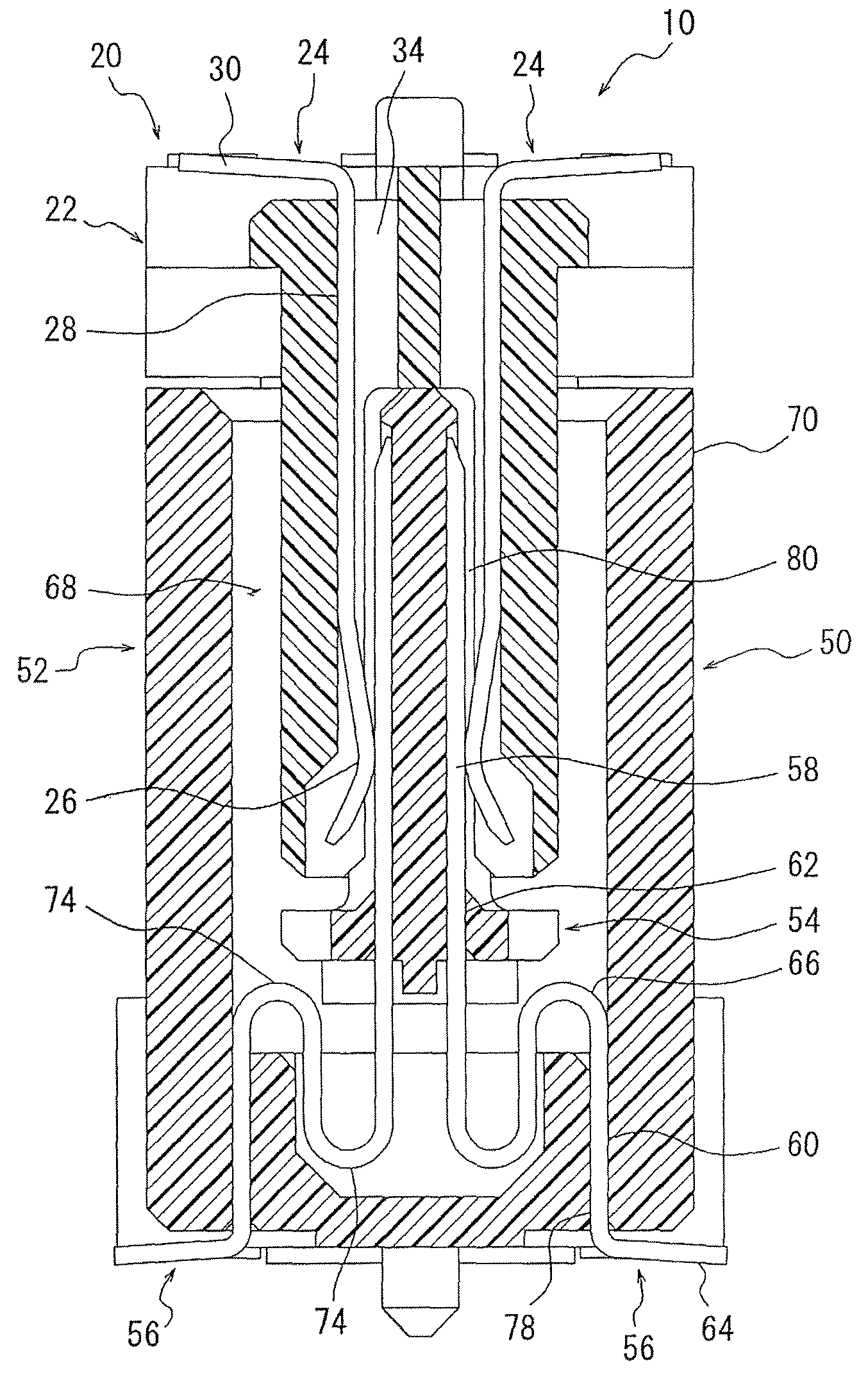
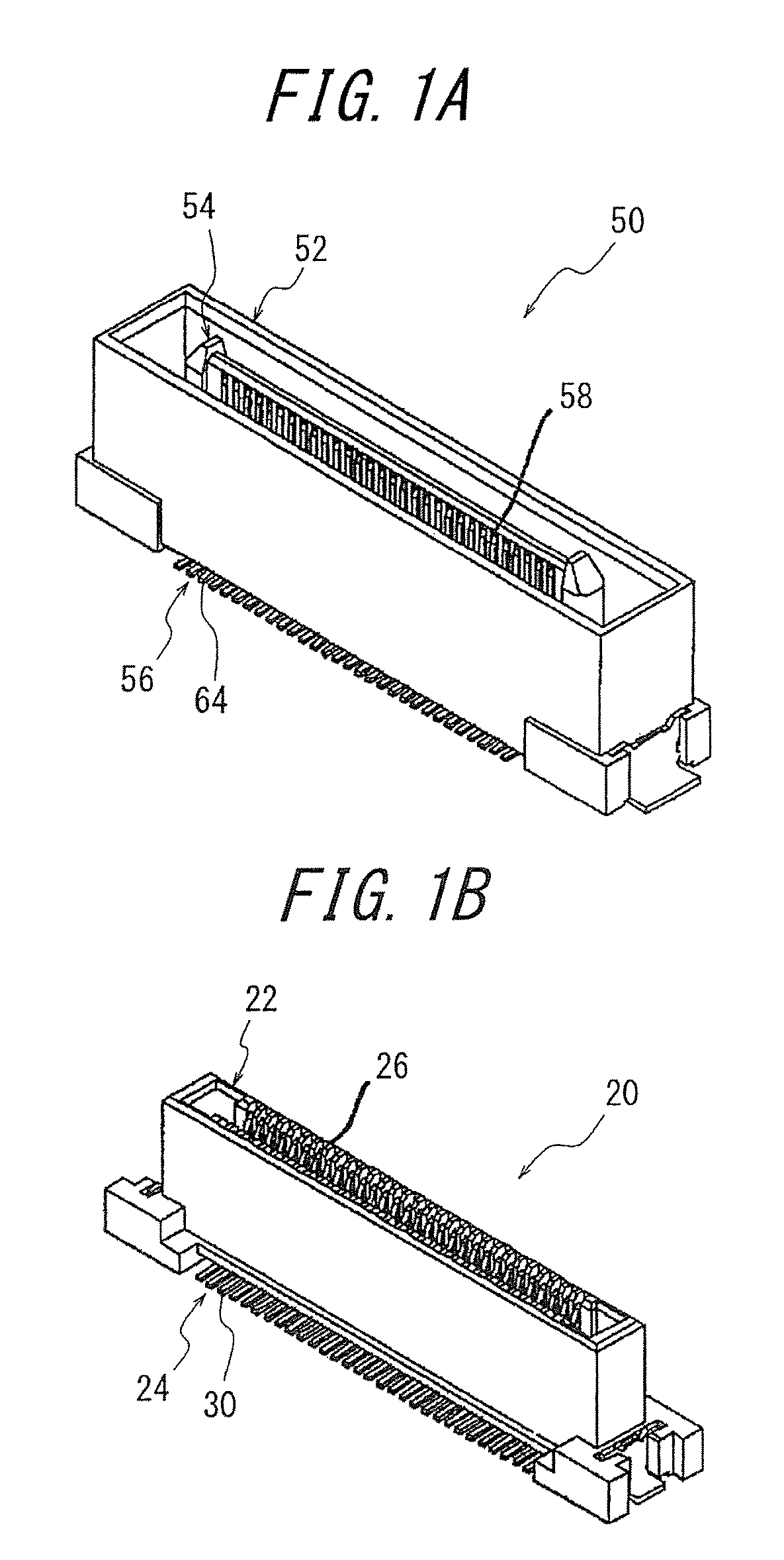
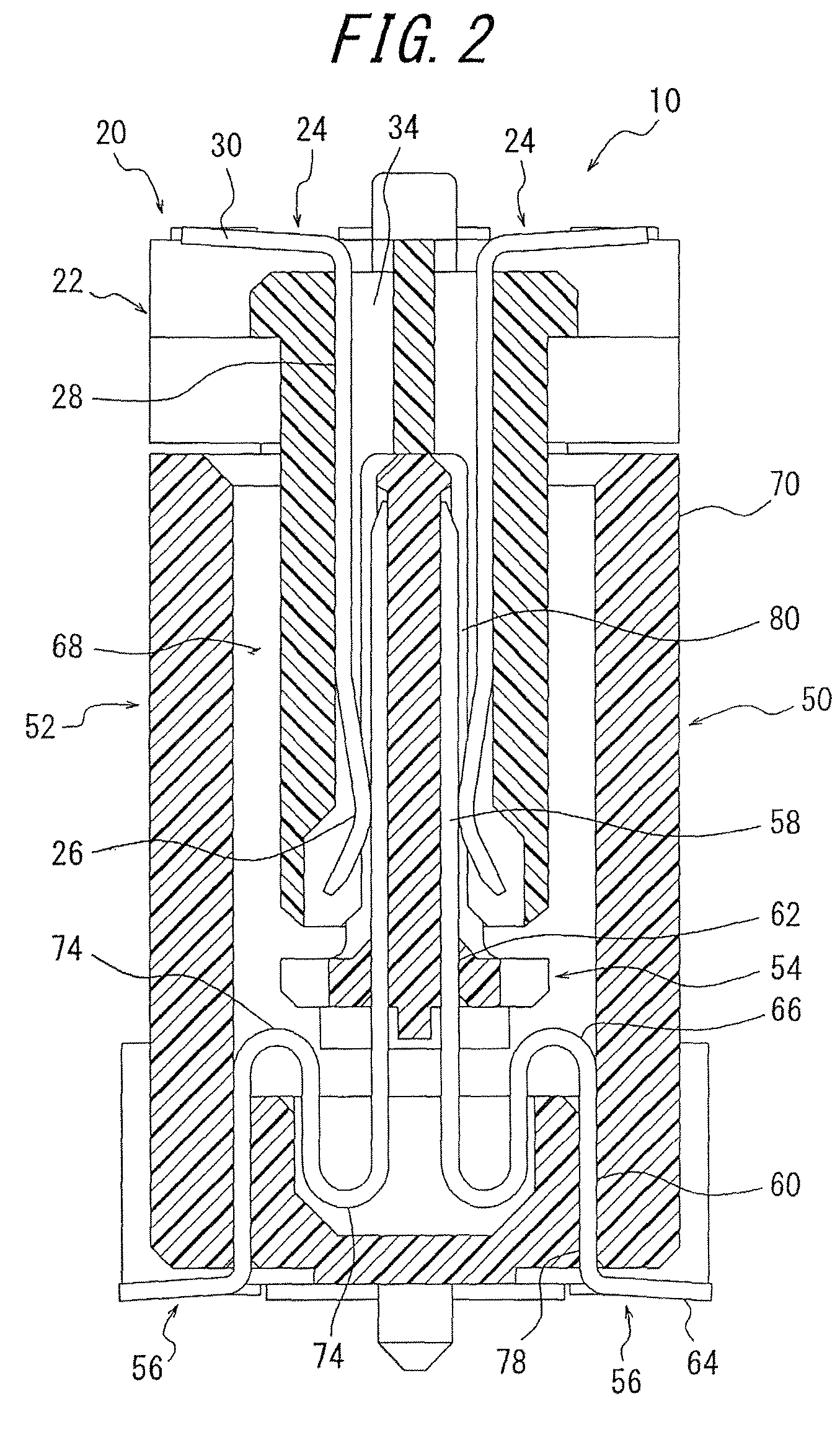
[0039]The important aspect of the invention lies in the electrical connector 10 consisting of a plug connector 50 and a receptacle connector 20 detachably fitted with each other, said receptacle connector 20 including a plurality of receptacle contacts 24 each having a first contact portion 26 adapted to contact a mating contact, a first fixed portion 28 to be fixed to a block 22, and a first connection portion 30 to be connected to a substrate 90, and the block 22 for arranging and holding said receptacle contacts 24, and said plug connector 50 including a plurality of plug contacts 56 each having a second contact portion 58 adapted to contact said receptacle contact 24, second and third fixed portions 60 and 62 to be fixed to a housing 52 and an insulator 54, respectively, and a second connection portion 64 to be connected to a substrate 90, and the housing 52 and the insulator 54 for arranging and holding said plug contacts 56, wherein each of said plug contacts 56 is provided be...


PUM


Abstract

An electrical connector consists of a plug connector and a receptacle connector to be fitted. An insulator is supported only by plug contacts each provided between second and third fixed portions with an elastic portion having at least one snaked portion so as to be floating in a housing. The shape of the second contact portion of each of the plug contacts is substantially in the form of a plate-shaped piece so that the second contact portion of the plug contact and the first contact portion of a receptacle contact are caused to contact each other in line contact at one location, and the elastic portion is arranged within a range from a position below the second contact portion to a position below the insulator. The electrical connector thus constructed is superior in resistance to vibration, and achieves space-saving and floating of the insulator.

Description

BACKGROUND OF THE INVENTION[0001]This invention relates to an electrical connector for use in electric and electronic appliances such as industrial machines, car navigation systems, and the like, and more particularly to an electrical connector superior in resistance to vibration and enabling floating of a part in the connector even when a space-saving is achieved (width dimension in a fitted state being less than 5 mm).[0002]In hitherto used electrical connectors having a floating part, two insulators have often been used, either of which is supported only by contacts having an elastic portion which is elastically deformable. It has been found that in order to provide an elasticity to contacts, elastic portions of the contacts are snaked or curved, or the contacts are elongated by increasing a distance between two insulators.[0003]As examples of prior art electrical connectors, incorporated herein are Japanese Patent Application Opened No. 2002-42,937 (Patent Literature 1), Japanes...

Claims


Application Information

Patent Timeline
Patent Type & Authority Patents(United States)
IPC IPC(8): H01R12/00
CPCH01R12/716H01R13/41H01R13/6315
Inventor FUKAZAWA, TAKEKIYOSHIMI, TAKANOBU
Owner DDK LTD
Why Eureka
Try Eureka