Speed change control device for automatic transmission and control method thereof

a technology of automatic transmission and control device, which is applied in the direction of gearing control, gearing element, belt/chain/gearing, etc., can solve the problem of shift busyness and make the driver feel uncomfortable, and achieve the effect of preventing rapid changes in the gear position

Active Publication Date: 2011-01-04
JATCO LTD +1
View PDF22 Cites 6 Cited by
  • Summary
  • Abstract
  • Description
  • Claims
  • Application Information

AI Technical Summary

Benefits of technology

[0004]An object of this invention is to suppress the sense of discomfort felt by a driver as a result of shift busyness while maintaining the auto upshift function of the gear position.
[0006]According to this invention, when it is determined that the input shaft rotation speed of the transmission following a downshift is greater than the rotation speed limit value, a downshift is performed to a gear position at which the input shaft rotation speed of the transmission falls below the post-downshift rotation speed, and thus a situation in which the input shaft rotation speed of the transmission reaches an auto upshift rotation speed such that an upshift is performed immediately after the downshift can be prevented. As a result, the sense of discomfort felt by a driver due rapid changes in the gear position can be prevented.

Problems solved by technology

In the prior art described above, when a downshift is performed to the vicinity of running conditions at which an auto upshift is performed, the auto upshift is performed immediately thereafter, and the resulting shift busyness makes the driver feel uncomfortable.

Method used


Image

  • Speed change control device for automatic transmission and control method thereof
  • Speed change control device for automatic transmission and control method thereof
  • Speed change control device for automatic transmission and control method thereof

Examples


first embodiment

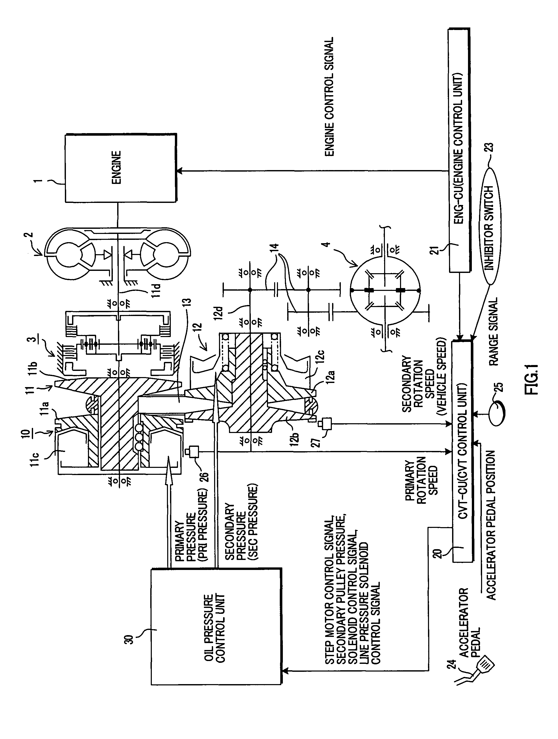
[0013]FIG. 1 is a schematic diagram showing a speed change control device for an automatic transmission according to an embodiment. A belt type continuously variable transmission 10 comprises a primary pulley 11, a secondary pulley 12, a V belt 13, a CVT control unit 20 (CVTCU hereafter), and an oil pressure control unit 30.

[0014]The primary pulley 11 is an input shaft side pulley which inputs the rotation of an engine 1 into the belt type continuously variable transmission 10. The primary pulley 11 comprises a fixed conical plate 11b which rotates integrally with an input shaft 11d, and a movable conical plate 11a which is disposed opposite the fixed conical plate 11b to form a V-shaped pulley groove, and which can be displaced axially by oil pressure acting on a primary pulley cylinder chamber 11c. The primary pulley 11 is connected to the engine 1 via a forward-reverse switching mechanism 3 and a torque converter 2 comprising a lockup clutch, and inputs the rotation of the engine...

second embodiment

[0047]In this embodiment, the constitution of the speed change control device for an automatic transmission is identical to that of the first embodiment, but the control content is different. Below, identical parts to those of the first embodiment have been allocated identical reference symbols, and description thereof has been omitted where appropriate.

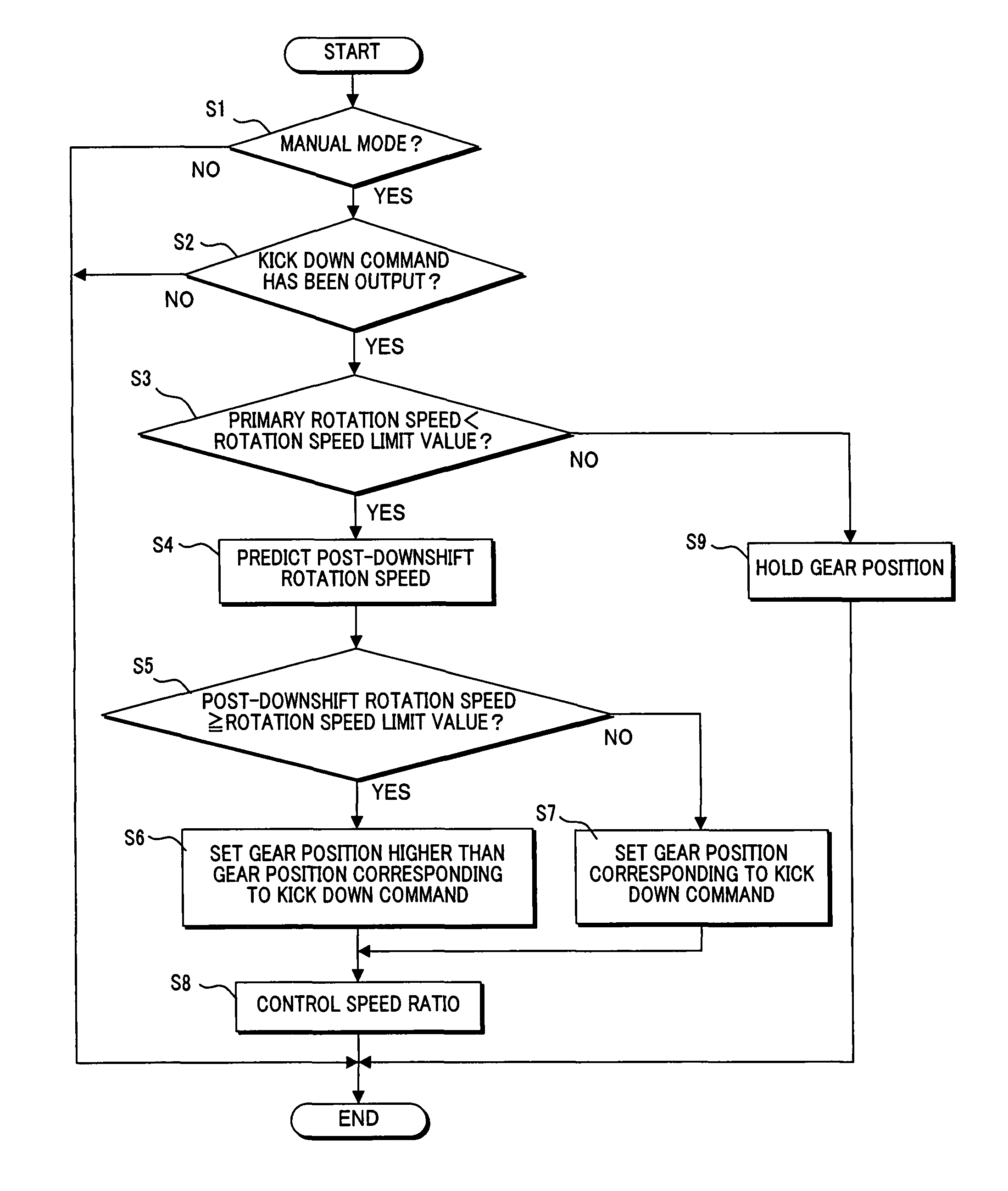
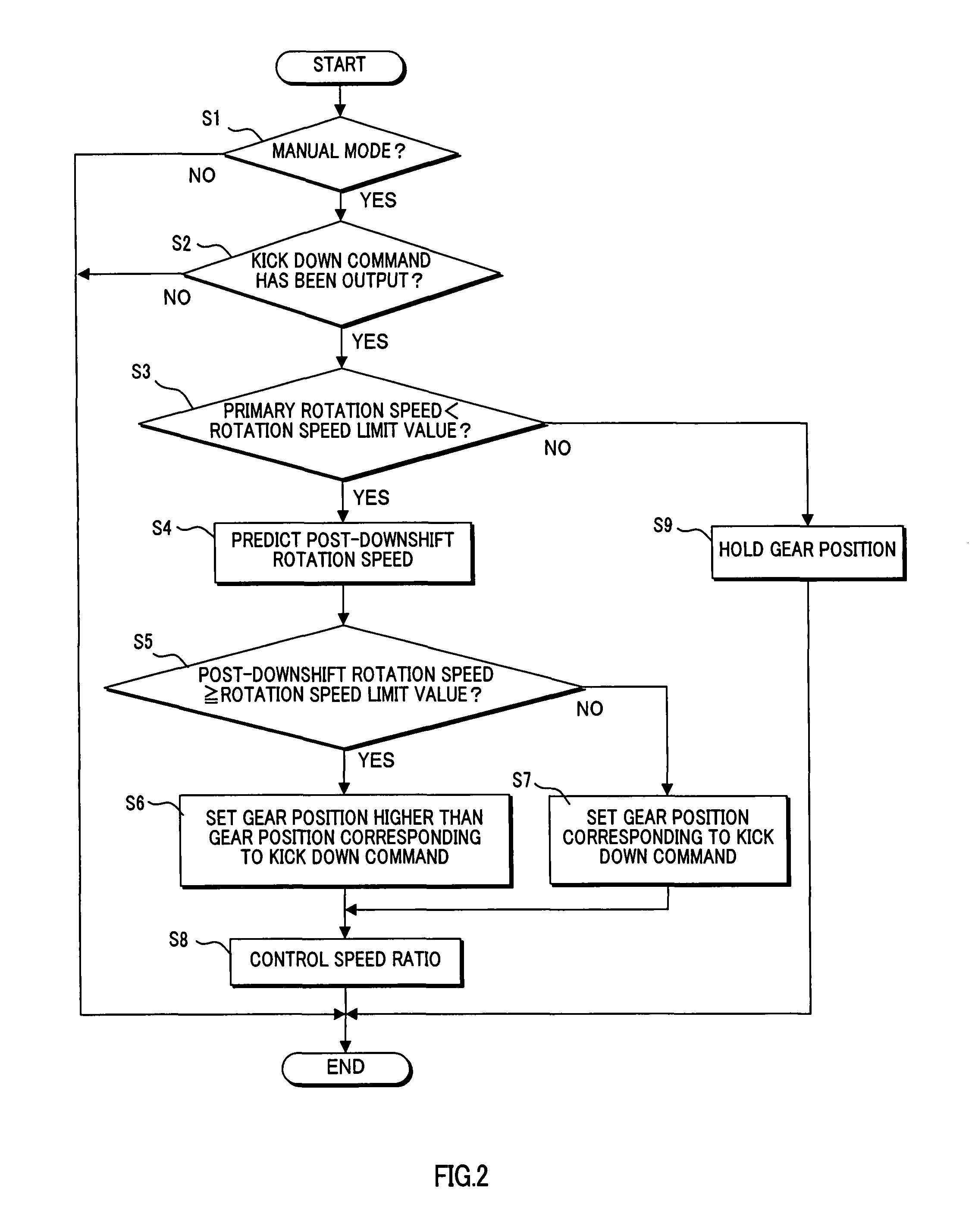
[0048]Referring to the flowchart in FIG. 5, the control performed by the CVTCU 20 according to this embodiment will be described. FIG. 5 is a flowchart showing the control of the speed change control device for an automatic transmission according to this embodiment. This control is performed repeatedly at brief intervals (of 10 ms, for example).

[0049]In a step S11, a determination is made as to whether or not the speed change mode is set to the manual mode. When it is determined that the manual mode has been set, the routine advances to a step S12, and when it is determined that the manual mode has not been set, the processing is ter...


PUM


Abstract

A speed change control device for an automatic transmission according to this invention determines whether or not a request to downshift a gear position of the transmission exists during traveling in a manual speed change mode (S1, S2), and calculates an input shaft rotation speed of the transmission following a downshift based on the downshift request (S4). When it is determined that the calculated rotation speed is higher than a rotation speed limit value (S5), the speed change control device performs a downshift to a gear position at which the input shaft rotation speed of the transmission is lower than the calculated rotation speed (S6, S8).

Description

FIELD OF THE INVENTION[0001]This invention relates to the speed change control of a speed change control device for an automatic transmission, and more particularly speed change control performed in a manual mode.BACKGROUND OF THE INVENTION[0002]JP10-141485A published by the Japan Patent Office describes a vehicle installed with an automatic transmission comprising a manual mode in which the gear position can be selected freely in accordance with the intent of a driver. According to another known technique for improving drivability, the gear position is upshifted (an auto upshift is performed) in accordance with the engine rotation speed and so on even when the driver is currently selecting a certain gear position in the manual mode, and thus an increase in engine rotation speed is prevented until fuel is cut in order to protect the engine and transmission.SUMMARY OF THE INVENTION[0003]In the prior art described above, when a downshift is performed to the vicinity of running conditi...

Claims


Application Information

Patent Timeline
Patent Type & Authority Patents(United States)
IPC IPC(8): F16H61/16
CPCF16H61/66259F16H59/20F16H59/42F16H61/16Y10T477/62427F16H2061/6617Y10T477/693675Y10T477/6934
Inventor KIMURA, YUSUKEKOBAYASHI, ATSUFUMIOCHIAI, TATSUOWAKABAYASHI, SHUICHIMAKIYAMA, AKIHIROKADONO, RYOJI
Owner JATCO LTD
Why Eureka
Try Eureka