Control device of hybrid vehicle

a control device and hybrid technology, applied in the direction of vehicle position/course/altitude control, process and machine control, instruments, etc., can solve the problem of more unsuitable shift position for high vehicle speed travel, and achieve the effect of suppressing driver discomfort and improving fuel economy

Active Publication Date: 2016-09-06
TOYOTA JIDOSHA KK
View PDF9 Cites 6 Cited by
  • Summary
  • Abstract
  • Description
  • Claims
  • Application Information

AI Technical Summary

Benefits of technology

[0008]Abnormal noise, such as a muffled sound or a rattling noise, arises through transmission, to a mechanical mechanism such as a gearbox or the like, of fluctuations in engine torque, which is a vibration source. This noise is deemed to be caused by gear rattle in a mechanical mechanism (for instance, between gears), such that the gear rattle sound is transmitted to the body by way of the mechanical mechanism, brakes, a parking brake and the like, and reaches the driver in the form of abnormal noise. Accordingly, the degree to which the abnormal noise reaches the driver depends on the state of the mechanical mechanism, the brakes and the parking brake. Therefore, it is possible to improve the fuel economy of a hybrid vehicle, while suppressing discomfort to the driver due to abnormal noise, by operating the engine taking into account the degree to which abnormal noise reaches the driver, in accordance with the state of such mechanical mechanism, brakes or parking brake.
[0009]The control device of a hybrid vehicle of the invention aims at improving the fuel economy of a hybrid vehicle while suppressing discomfort to the driver due to abnormal noise.

Problems solved by technology

This noise is deemed to be caused by gear rattle in a mechanical mechanism (for instance, between gears), such that the gear rattle sound is transmitted to the body by way of the mechanical mechanism, brakes, a parking brake and the like, and reaches the driver in the form of abnormal noise.
In sequential shift (virtual shift), the further the shift position is on the low vehicle speed range, the more unsuitable the shift position becomes for travel at a high vehicle speed.

Method used


Image

  • Control device of hybrid vehicle
  • Control device of hybrid vehicle
  • Control device of hybrid vehicle

Examples


first embodiment

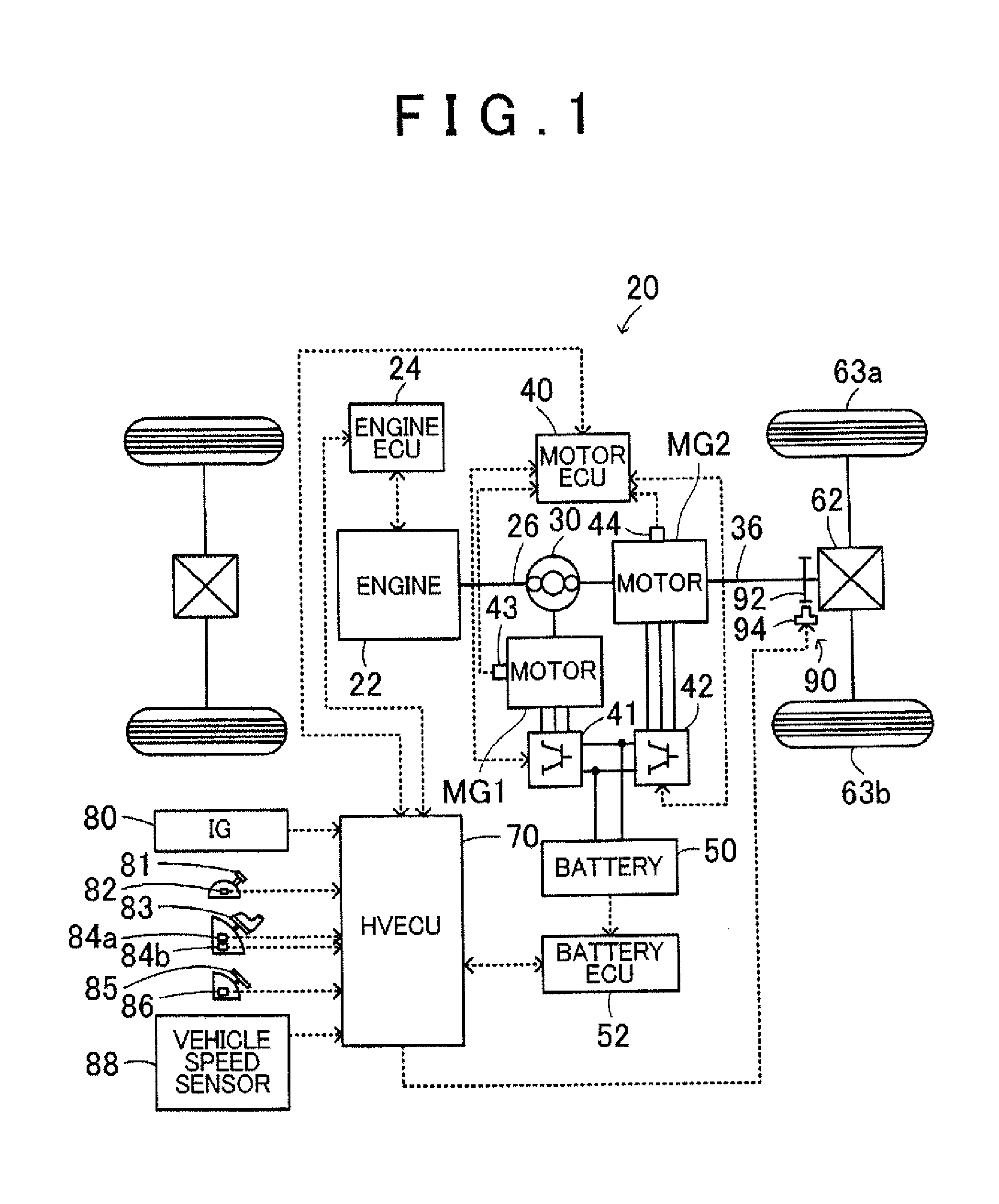
[0033]The HV ECU 70, the engine ECU 24, the motor ECU 40 and the battery ECU 52 correspond to the control unit of a vehicle of the

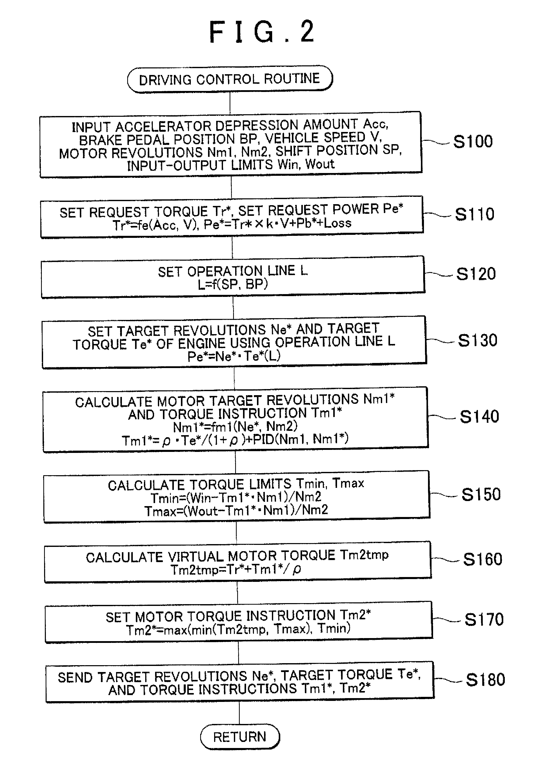
[0034]In the hybrid automobile 20 of the first embodiment, a request torque to be outputted to the drive shaft 36 is calculated on the basis of the accelerator depression amount Acc corresponding to the depression amount of the accelerator pedal 83 by the driver, and on the basis of the vehicle speed V. The operation of the engine 22, the motor MG1 and motor MG2 is controlled next in such a manner that a request motive power corresponding to the request torque is outputted to the drive shaft 36. Operation control of the engine 22, the motor MG1 and the motor MG2 include, for instance, a torque conversion operation mode, a charge and discharge operation mode and a motor operation mode. In the torque conversion operation mode, the operation of the engine 22 is controlled in such a manner that the engine 22 outputs motive power commensurate with the request ...

second embodiment

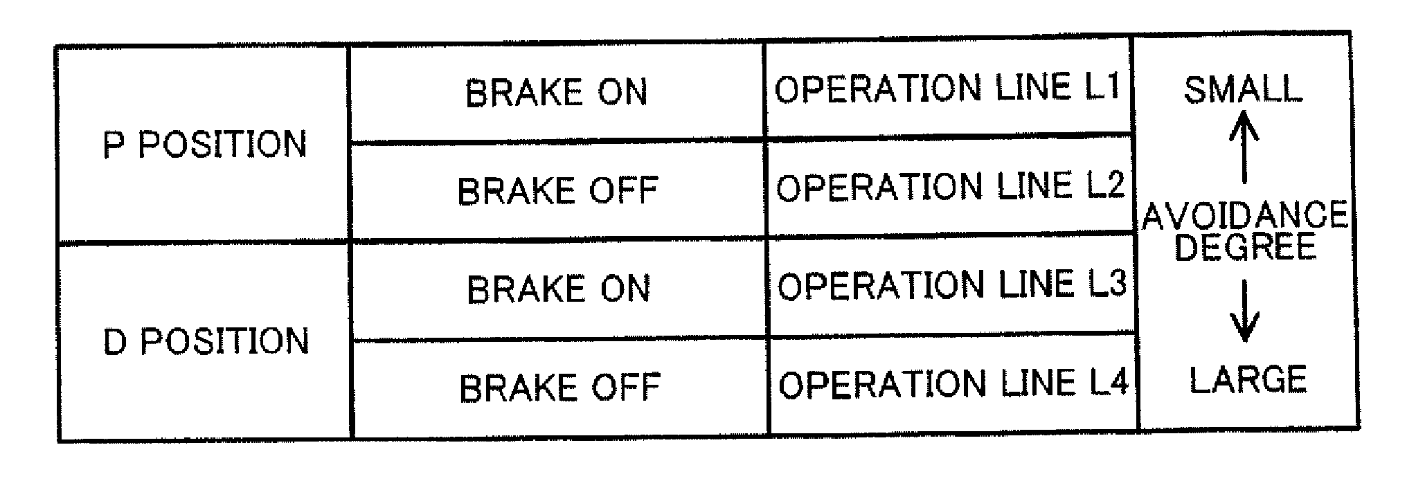
[0048]The automatic transmission 98 of the hybrid automobile 220 of the second embodiment is connected to an input shaft 36a, to which there are connected the ring gear of the power distribution and integration mechanism 30 and the rotor of the motor MG2, and to an output shaft 36b that is connected to the drive wheels 63a, 63b, via the differential gear 62. The automatic transmission 98 is configured in the form of a conventional hydraulically-driven four-speed automatic transmission in which there is selected any one from among neutral and first to fourth speeds. The automatic transmission 98 is controlled by the HV ECU 70 in such a manner that the shift position SP changes to neutral when at the N position or the P position; when the shift position SP is at the D position, the automatic transmission 98 is controlled through upshifting or downshifting to any from among a corresponding first to fourth speed on the basis of a conventional shift line (three upshift lines and three do...


PUM


Abstract

An operation line is set on the basis of a shift position and a brake pedal position, from among a plurality of operation lines in which a degree of avoidance of an abnormal noise generation region from a fuel-economy optimal operation line becomes smaller as a degree to which travel of the vehicle is restricted becomes greater. An engine and a motor are controlled by setting a target operation point of the engine using the set operation line, and by setting a torque instruction of the motor.

Description

CROSS REFERENCE TO RELATED APPLICATIONS[0001]This application claims priority to Japanese Patent Application No. 2011-208163 filed on Sep. 22, 2011, which is incorporated herein by reference in its entirety including the specification, drawings and abstract.INCORPORATION BY REFERENCE[0002]The disclosure of Japanese Patent Application No. 2011-208163 filed on Sep. 22, 2011 including the specification, drawings and abstract is incorporated herein by reference in its entirety.BACKGROUND OF THE INVENTION[0003]1. Field of the Invention[0004]The invention relates to a vehicle control device, and more particularly, to a control device of a hybrid vehicle that is provided with an internal combustion engine, a power generator capable of input and output of motive power, a planetary gear mechanism in which three rotational elements are connected to three shafts, namely a drive shaft that is coupled to an axle, an output shaft of the internal combustion engine and a rotating shaft of the power...

Claims


Application Information

Patent Timeline
Patent Type & Authority Patents(United States)
IPC IPC(8): B60W20/00B60W10/08B60W10/06B60K6/445B60W30/188B60W30/18B60L50/16
CPCB60W10/06B60K6/445B60W10/08B60W20/17B60W30/18054B60W30/1882B60W2510/188B60W2710/083Y02T10/6239Y02T10/6286Y02T10/62B60W20/15
Inventor MUTA, KOICHIRONAKAMURA, MICHIO
Owner TOYOTA JIDOSHA KK
Why Eureka
Try Eureka