
Power unit and safety circuit having the same

a technology of safety circuit and power unit, applied in the direction of electric device, battery/fuel cell control arrangement, coupling device connection, etc., to achieve the effect of accurately grasping the operating condition and ensuring safety

Active Publication Date: 2011-01-04
GRUPO PETROTEMEX DE C V +1
View PDF5 Cites 3 Cited by
  • Summary
  • Abstract
  • Description
  • Claims
  • Application Information

AI Technical Summary

Benefits of technology

The present invention is about a power unit made up of multiple battery modules that can be safely maintained. It includes a cover that can be opened and closed to access the battery modules, and a safety switch that can be opened and closed by inserting and removing a service plug. The power unit also has a safety circuit that can detect the removal of the service plug and disconnect the power unit from the load. This invention ensures safety during maintenance and accurately monitors the operating condition of the power unit.

Problems solved by technology

However, a problem may arise when a terminal cover is removed during operation for performing maintenance and check on the neighborhood of the positive and negative external connection terminals of the battery modules.

Method used


Image

  • Power unit and safety circuit having the same
  • Power unit and safety circuit having the same
  • Power unit and safety circuit having the same

Examples


Embodiment Construction

[0036]An embodiment of the present invention will be described hereunder by reference to the drawings.

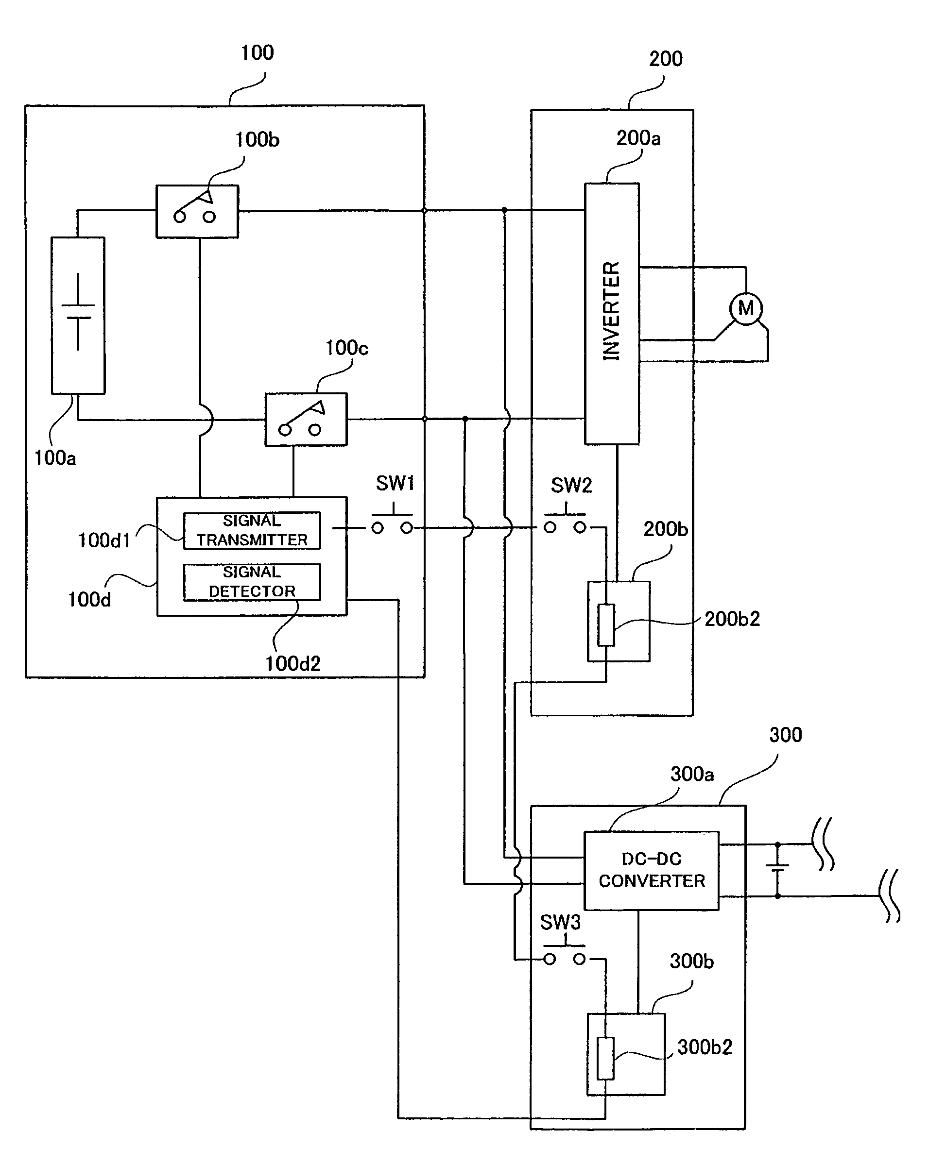
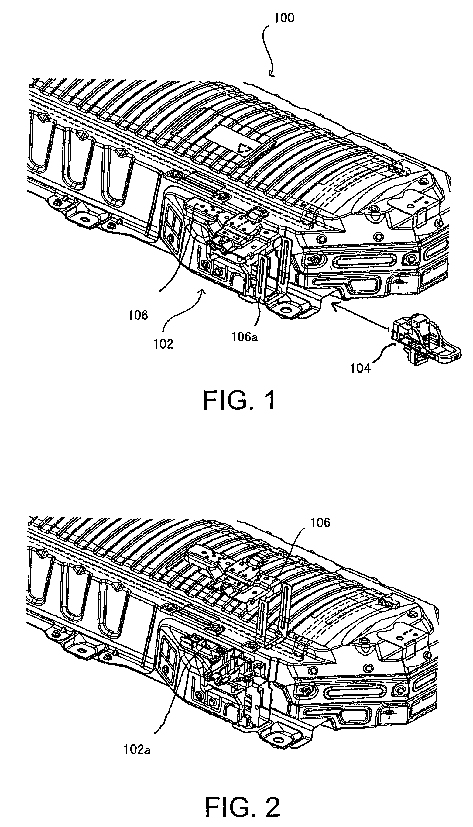
[0037]FIG. 1 shows the configuration of a battery pack 100 serving as a power unit of a present embodiment for driving a vehicle. The basic configuration of the battery pack 100 is identical with that of a related-art battery pack shown in FIG. 6. A plurality of battery modules made up of one cell or a plurality of series-connected cells are arranged in parallel with cooling passages interposed therebetween. The battery pack includes a built-in battery assembly constructed by binding and assembling end members disposed at both ends of the battery modules and connecting the battery modules in series with each other. A cooling air ventilation passage for supplying and exhausting a cooling air to and from the respective cooling passages provided between the battery modules is laid in upper and lower portions of the battery assembly. A charge / discharge monitoring section (a battery ECU)...


PUM


Abstract

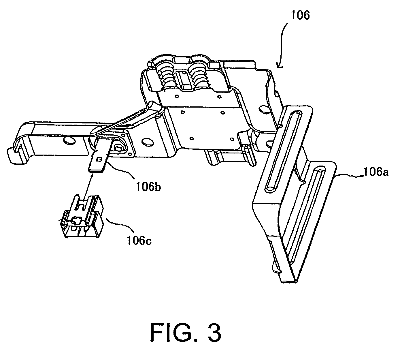
A power unit including a plurality of series-connected battery modules and safety circuit wherein a service plug is inserted from the side of a terminal board of a battery pack, thereby establishing an electrical connection among battery modules. A connector is provided on a back of a terminal cover by way of a projecting section, and a second safety switch is activated by attachment of a terminal cover and insertion of the connector to the terminal board, thereby establishing an electrical connection among the battery modules. Even when the service plug is attached at the time of completion of maintenance without attachment of the terminal cover, the battery modules are still kept in an unconnected state by means of a second switch, and energization, which would otherwise arise with exposed terminals, is prevented.

Description

PRIORITY INFORMATION[0001]This application claims priority to Japanese Patent Application No. 2007-217784 filed on Aug. 24, 2007, which is incorporated herein by reference in its entirety.BACKGROUND OF THE INVENTION[0002]1. Technical Field[0003]The present invention relates to a power unit and a safety circuit having the same, and more particularly to a structure for preventing an electric shock, which would otherwise arise during maintenance operation[0004]2. Related Art[0005]In a hybrid electric vehicle, or the like, using a power unit assembled by a series connection of a plurality of battery modules, each of which consists of one cell or a plurality of cells, provision of only a power switch for opening or closing a current-carrying circuit originating from a power unit is assumed not to prevent erroneous activation of a power switch during maintenance operation. For this reason, provision of an interlock mechanism separate from the power switch has been proposed.[0006]2001-3208...

Claims


Application Information

Patent Timeline
Patent Type & Authority Patents(United States)
IPC IPC(8): H02H11/00
CPCB60L3/0046B60L3/0069B60L3/04H01R13/701H01R13/713B60L58/26B60L58/18Y02T10/70
Inventor MARUKAWA, SHUHEIMIYAGI, YOSHIKAZUMATSUKAWA, YASUSHI
Owner GRUPO PETROTEMEX DE C V
Learn More