Cove base corner cover

a cove base and corner cover technology, applied in the field of cove bases, can solve the problems of high cost, difficult installation of cove bases at intersecting corners, and inconvenient installation of cove bases,

Inactive Publication Date: 2011-01-11
MEAHL GREGORY L
View PDF31 Cites 10 Cited by
  • Summary
  • Abstract
  • Description
  • Claims
  • Application Information

AI Technical Summary

Benefits of technology

[0013]in accordance with the present invention, both of the Cove base corner covers comprises an integrally formed cover for an external corner of cove base within an elongated midsection defining a pair of generally flat intersecting to thereby form an external vertex and a hollow interior that may be placed over an intermediate portion of cove base at internal and external corners. The corners also have a respective concave face extending downwardly and forwardly from each perpendicular face with the two concave faces intersecting to form a foreword projecting lower extension of the external vertex creating the cove elements having at least a portion of the interior base portion being hollow whereby the base portion may be placed over to adjoining cove portions of cove base at intersecting corners. The corner covers are athletically designed with an overall appearance resembling that of a pillar. It provides an improved method for use with installations of pre-manufactured base at intersecting corners. It extends slightly beyond the cove base it is attached over yet it structure depicts unity with its face extending a minimal distance beyond the corner so as not to appear obtrusive with the edges being tapered allowing it to blend in more readily. This allows for the overall appearance to exhibit completeness.

Problems solved by technology

Installing cove base at intersecting corners can be very difficult and time-consuming.
Coving is very difficult to install and requires a well-trained professional as well as being very expensive.
Inside and outside corners are very difficult to implement.
Nevertheless inside and outside corners can still be particularly troublesome and difficult to establish.
This process can be very frustrating and time-consuming taking many steps to accomplish the task.
This most often results with an undesirable appearance, being that the bottom cove portion collapses into itself.
If to much material is taken out, a hole is created on the front side, so consequently you must start over with a new piece and quite possibly the piece you have damaged may have to be discarded.
Reducing material from the back is imperative and invariably reduces the integrity at the corners vertex.
Another particular disadvantage and frustrating aspect of wrapping, is the pressure that is created at the top portion of the base from the vertex and for the most part, it routinely pops away at the top edge from the wall on one side or the other, if not on both sides.
Caulking is also generally used for filling in voids which create color match problems and eventually attracts dirt.
These are still time-consuming and the installer must be very precise.
Adjoining the mitered edges to align perfectly together is another problem in and of itself.
Again this is not only time-consuming, it does not address the problem of the lower portion cove collapsing into itself.
In actuality, the most common method adapted is to used a brad nail to hold the material in place, yet using this method usually leaves an indentation or even a hole.
6″ cove base is extremely difficult to wrap or miter.
Inconsistencies and variations of the walls increase with the height and take a great deal more effort as well as time to accomplish navigating around, into or from intersecting corners.
This requires time and effort especially if the wall itself requires preparation for fastening along with the installation of the fastening system.
These are very expensive and are not as simple in their use.

Method used


Image

  • Cove base corner cover
  • Cove base corner cover
  • Cove base corner cover

Examples


Embodiment Construction

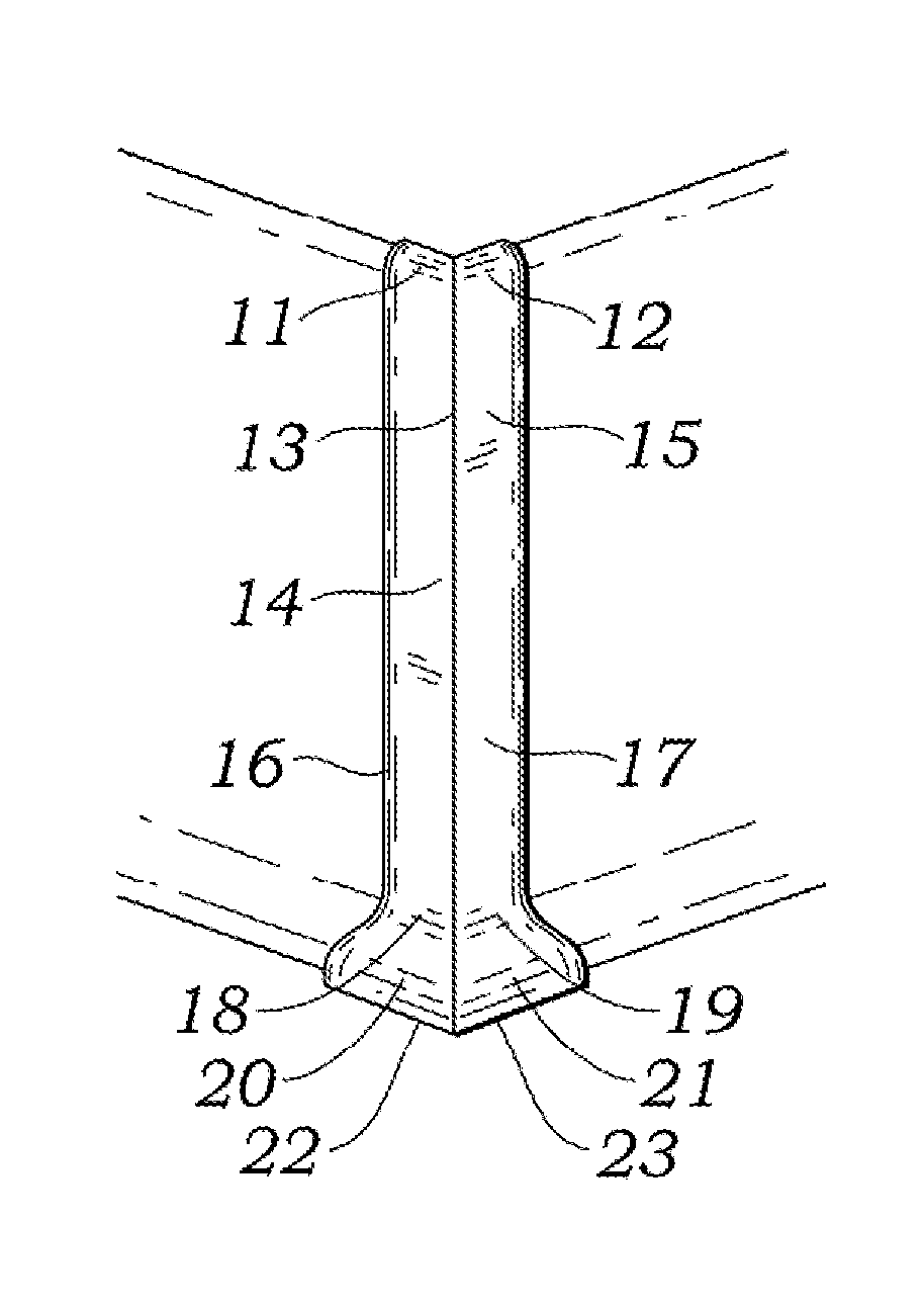
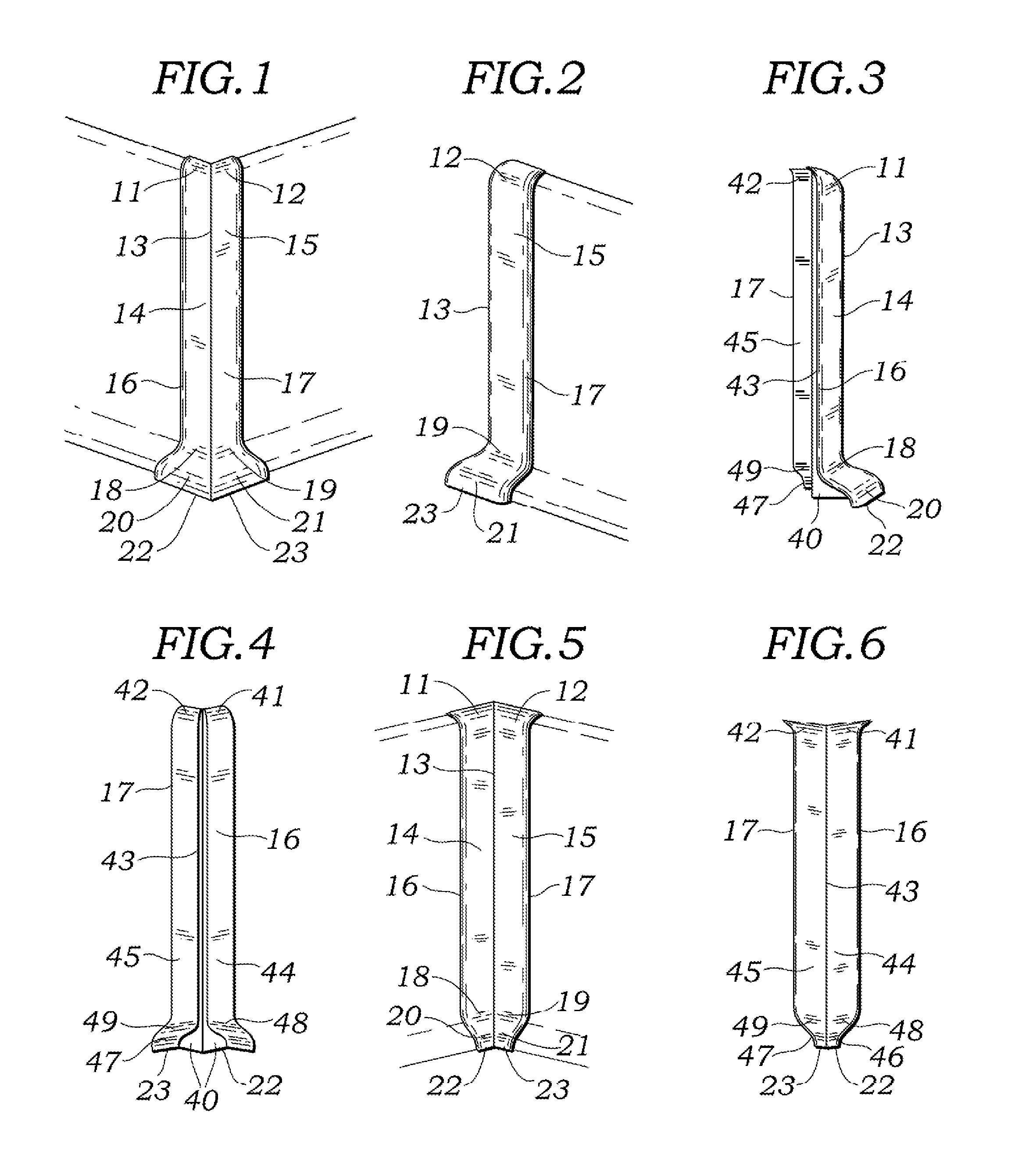
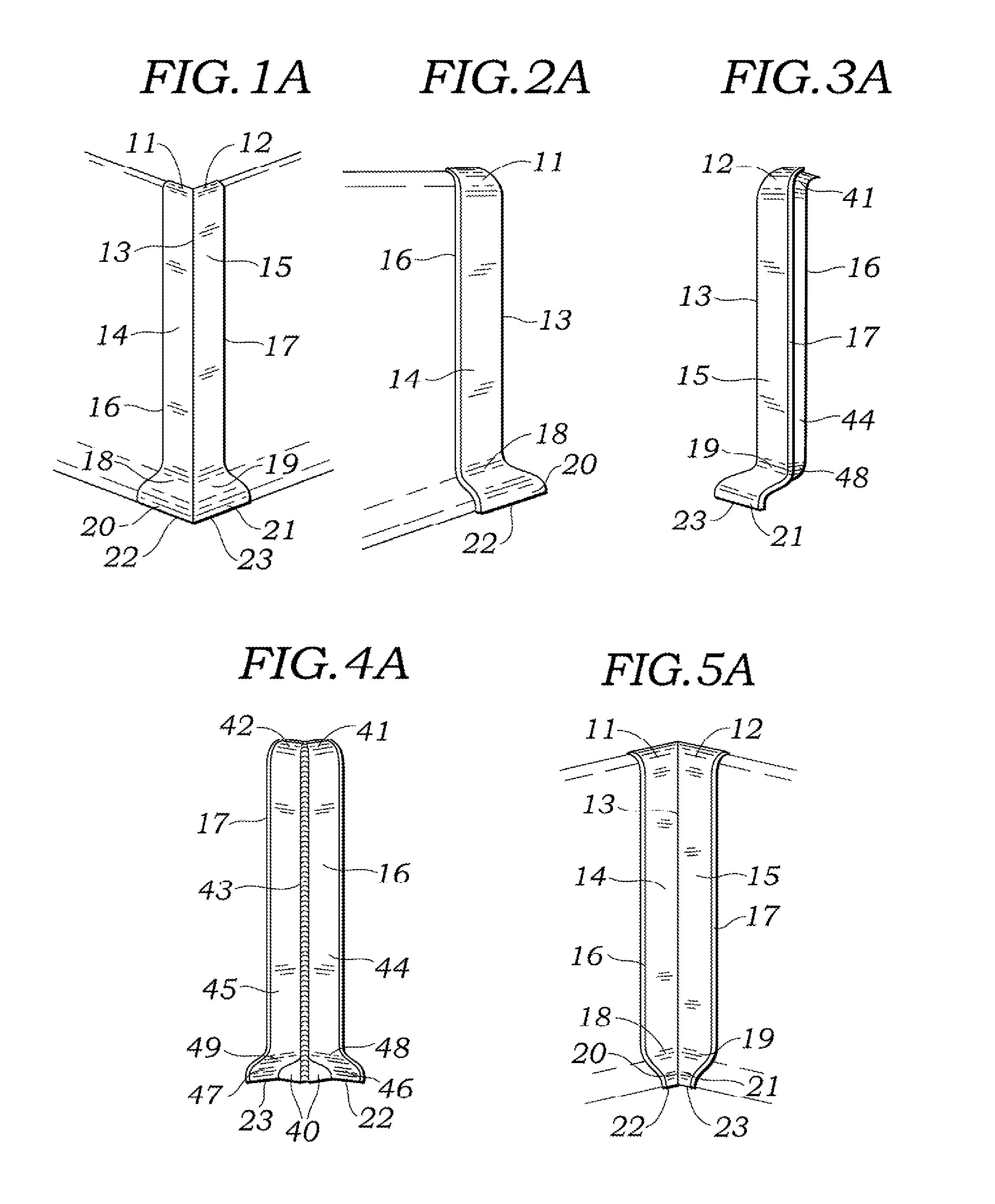
[0025]A preferred embodiment of the corner cover of the present invention is illustrated in FIGS. 1,2,3 and 4, outside corner cover, and 5&6, inside corner cover. The cover has an integrally formed elongated body comprised of thin walls. I prefer the thickness of these walls to be between 0.10 and 0.125 of an inch along with being tapered round to the edges. However the thickness can be varied as thin as a piece of tin or sheet metal or as thick up to ½ of an inch, depending on what is called for. An example would be for use as a very durable corner protector. Each side should be of sufficient horizontal width to overlap and cover cuts made without exact precision.

[0026]There is no one preferred color for the Cove base corner cover. The actual preferred color would be that of the cove base it is being placed over. Matching the color would be ideal, however a color of similar resemblance would suffice quite well. Depending on the shading of light, a perfect match often appears to hav...


PUM


Abstract

Two integrally formed multipurpose devices with the resemblance of an aesthetic pillar hollowed out incorporating a cove element at the lower portion that is preformed to fit over and cover intersecting corners of previously installed cove base used in the flooring industry. The Cove base corner cover provides a unified junction between the two adjacent sides of a corner. This invention also provides an inexpensive, simplistic and productive procedure for installations of inside and outside corners. Precision cuts along with most all of the numerous steps currently being utilized to navigate into or from and around intersecting corners is eliminated. The problems such as, the cove element collapsing into itself as well as the popping of the upper edge associated with wrapping cove base around a corner, is also eliminated and for the most part, frustration and aggravation incurred while facilitating installations at the corners is significantly reduced. Repairs of damaged, cracked and split corners of already existing wall coverings are easily achieved with the use of the Cove base corner cover along with adapting the purpose as a corner protector while ultimately providing a final presentation of a well-designed and high-quality end result.

Description

BACKGROUND OF INVENTION[0001]1. Field of Invention[0002]This invention relates to cove base, also referred to as wall base, rubber / vinyl base, vinyl mop base, and top set within the classification of wall coverings in the flooring industry. Specifically to the installation and repairs and of cove base at intersecting corners.[0003]2. Prior Art[0004]Installing cove base at intersecting corners can be very difficult and time-consuming. Even the professional can dread the procedure of installing cove base after installing the floor covering. In the flooring industry coving was introduced during the period when linoleum based flooring was being predominately used as a hard surface floor covering. Today the primary substitute is vinyl based resilient floor covering. The term coving is used to describe flooring extending from the floor at the edges and traversing up the wall in one continuous piece of material. At the apex where the floor and wall converge, the material is curved creating...

Claims


Application Information

Patent Timeline
Patent Type & Authority Patents(United States)
IPC IPC(8): E04B2/00
CPCE04F19/04E04F19/028E04F19/0477E04F2019/0413E04F2019/0454E04F2019/0422
Inventor MEAHL, GREGORY L.
Owner MEAHL GREGORY L
Why Eureka
Try Eureka