Traveling apparatus

a technology of traveling apparatus and moving parts, which is applied in the direction of transportation and packaging, electric propulsion mounting, bicycles, etc., can solve the problems of difficult control, complicated measures, and the movement of the load generated by the driver

Inactive Publication Date: 2011-01-11
TOYOTA JIDOSHA KK
View PDF15 Cites 48 Cited by
  • Summary
  • Abstract
  • Description
  • Claims
  • Application Information

AI Technical Summary

Benefits of technology

[0012]With this constitution, the conflict between a brake operation and an accelerator operation performed manually by a driver and primary travel control of the traveling apparatus is eliminated, and as a result, accelerator operations and brake operations (in other words, decelerator operation) performed manually by the driver can be used in combination with acceleration / deceleration control of the traveling apparatus.

Problems solved by technology

However, when the brake or the accelerator is operated manually in a traveling apparatus for a coaxial two-wheeled vehicle such as those described above, load movement is generated by the driver due to inertia when an operation is performed during travel, for example.
Therefore, two conflicting types of control are performed, and as a result, it may be impossible to realize smooth control, particularly in relation to manual operations.
Hence, to make manual brake and accelerator operations possible in a conventional traveling apparatus for a coaxial two-wheeled vehicle, complicated measures such as blocking travel control corresponding to driver load movement when a manual operation of the brake or accelerator is performed, for example, are required.
To realize such measures, a complicated control mechanism must be provided, and therefore manual brake and accelerator operations have not been realized in a conventional traveling apparatus for a coaxial two-wheeled vehicle.
This application has been designed in consideration of such points, and a problem to be solved thereby is that in a conventional apparatus, a manual operation of a brake or an accelerator conflicts with primary travel control through driver load movement, and therefore manual operations cannot be performed in combination with brake and accelerator control.

Method used


Image

  • Traveling apparatus
  • Traveling apparatus
  • Traveling apparatus

Examples


Embodiment Construction

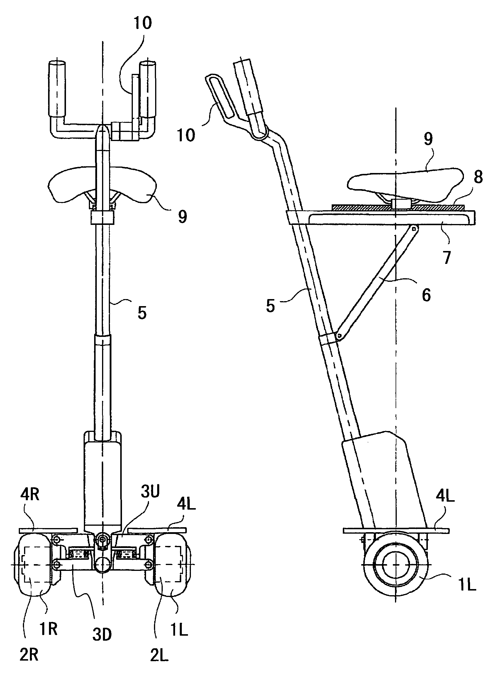
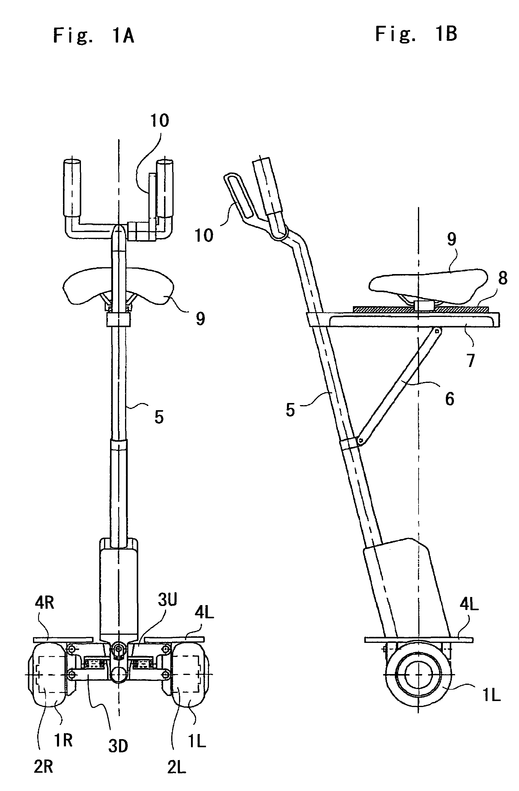
[0028]The present invention will be described below with reference to the drawings. FIGS. 1A and 1B are a front view and a side view showing the constitution of an embodiment of a coaxial two-wheeled vehicle to which a traveling apparatus according to the present invention is applied. Note that in FIGS. 1A and 1B, the main overall constitution is substantially identical to that of the apparatus disclosed in Japanese Unexamined Patent Application Publication No. 2005-6435.

[0029]In FIGS. 1A and 1B, two wheels 1L, 1R are disposed in parallel, and these wheels 1L, 1R are provided respectively with independent motors 2L and 2R. The motors 2L and 2R are connected by vehicle main bodies 3U and 3D divided into an upper side and a lower side. Although not shown in the drawing, a circuit apparatus such as a control circuit for controlling the tilt of the vehicle, which is detected by a sensor such as a gyro, and controlling driving of the motors 2L, 2R in accordance with information such as d...


PUM


Abstract

A coaxial two-wheeled vehicle includes a plurality of wheels disposed in parallel, a vehicle body, at least one of a step plate and a seat, an operating member, and a mechanism. The vehicle body supports plurality of wheels rotatably. The step plate is coupled to the vehicle body to carry a driver in an upright attitude. The seat is coupled to the vehicle body to seat the driver. The operating member is coupled to the vehicle body and operated by the driver for inputting driver's operation including an accelerating operation and a decelerating operation. The mechanism is configured to move at least one of the step plate and the seat in a front-rear direction of the vehicle body in accordance with an operation of the operating member.

Description

BACKGROUND OF THE INVENTION[0001]1. Field of the Invention[0002]The present invention relates to a traveling apparatus suitable for use in a coaxial two-wheeled vehicle having two wheels disposed on an identical axial center line, for example.[0003]2. Description of Related Art[0004]In a conventional coaxial two-wheeled vehicle, attitude control is performed on the vehicle mainly in a pitch axis direction by detecting the tilt of the vehicle using a plurality of gyros or the like (see U.S. Pat. No. 5,971,091, for example).[0005]An apparatus that performs travel control in a coaxial two-wheeled vehicle in accordance with load movement generated by a driver is also known (see Japanese Unexamined Patent Application Publication No. 2005-6435, for example).[0006]An apparatus in which a coaxial two-wheeled vehicle is provided with a seat has also been proposed (see Japanese Unexamined Patent Application Publication No. 2004-74814, for example).[0007]In a traveling apparatus for a coaxial ...

Claims


Application Information

Patent Timeline
Patent Type & Authority Patents(United States)
IPC IPC(8): B62D61/00B60K1/00
CPCB62D37/00B62D61/00B62K3/007B62K11/007
Inventor ISHII, SHINJIYAMANO, IKUO
Owner TOYOTA JIDOSHA KK
Why Eureka
Try Eureka