Step apparatus for heavy construction equipment and tree harvester having leveling system

a technology of construction equipment and step apparatus, which is applied in the direction of ladders, steps, constructions, etc., can solve the problems of interference or collision between the step apparatus, the operator's approach to the structure for getting on or off the equipment is lowered, and the maintenance and repair work becomes difficult, so as to remove interference or conflict

Inactive Publication Date: 2009-12-03
VOLVO CONSTR EQUIP
View PDF23 Cites 11 Cited by
  • Summary
  • Abstract
  • Description
  • Claims
  • Application Information

AI Technical Summary

Benefits of technology

[0022]One object of the present invention is to provide a step apparatus for heavy construction equipment and tree harvester having a leveling system, which can prevent a collision with a lower driving structure even if an upper frame is tilted by making a step frame kept in a step protector in a foldable manner and making the step frame form stairs on an outer side of the upper frame when in use.
[0023]Another object of the present invention is to provide a step apparatus for heavy construction equipment and tree harvester having a leveling system, which can remove interference or conflict between the step apparatus and the lower driving structure and collision between the step apparatus and an external object even if the upper frame is tilted by forming inclined steps that are projected to a side of the upper frame to secure the visual field of an operator.
[0024]Still another object of the present invention is to provide a step apparatus for heavy construction equipment and tree harvester having a leveling system, which can selectively adjust the keeping and exposing of a step frame by hydraulic pressure when a safety lever is set to a safety mode.

Problems solved by technology

According to the heavy construction equipment and tree harvester having a leveling system as described above, since the height of structures mounted on the upper frame, such as the cab, engine room, and the like, is relatively high, the operator's approach to such structure for getting on or off the equipment is lowered, and the maintenance and repair work becomes difficult.
However, the conventional step apparatus has the problem that, although the fixing position of the step frame 7 is adjusted, the step apparatus 10 is still exposed to an outside, and thus interference or collision may occur between the step apparatus and an external object or the lower driving structure.
For example, the conventional fixed step apparatus has severe problem that, when the upper swing structure and the upper frame are inclined or tilted at a preset angle due to an inclined ground surface, the step frame is projected toward the lower driving structure, and thus collision occurs between one side of the step frame and the lower driving structure to cause damage of the step frame and the lower driving structure.
Also, even in the case where the conventional step apparatus is fixed to the upper part of the upper frame in a standing posture by the stoppers to prevent collision between the step frame and the lower driving structure, collision may still occur between the step frame and an external object during working of the equipment.
The conventional fixed step apparatus also has severe problems that, in the case of adjusting the setting position of the step apparatus before leveling control of the upper frame or during working of the equipment, an operator should manually adjust the positions of the step frame and the steps up and down in a state where the operator directly hangs on the upper frame, and thus the manipulation performance is lowered with the operator's safety threatened.

Method used


Image

  • Step apparatus for heavy construction equipment and tree harvester having leveling system
  • Step apparatus for heavy construction equipment and tree harvester having leveling system
  • Step apparatus for heavy construction equipment and tree harvester having leveling system

Examples


Embodiment Construction

[0067]Hereinafter, a leveling apparatus for excavator and forestry machine equipment according to preferred embodiments of the present invention will be described with reference to the accompanying drawings. The matters defined in the description, such as the detailed construction and elements, are nothing but specific details provided to assist those of ordinary skill in the art in a comprehensive understanding of the invention, and thus the present invention is not limited thereto.

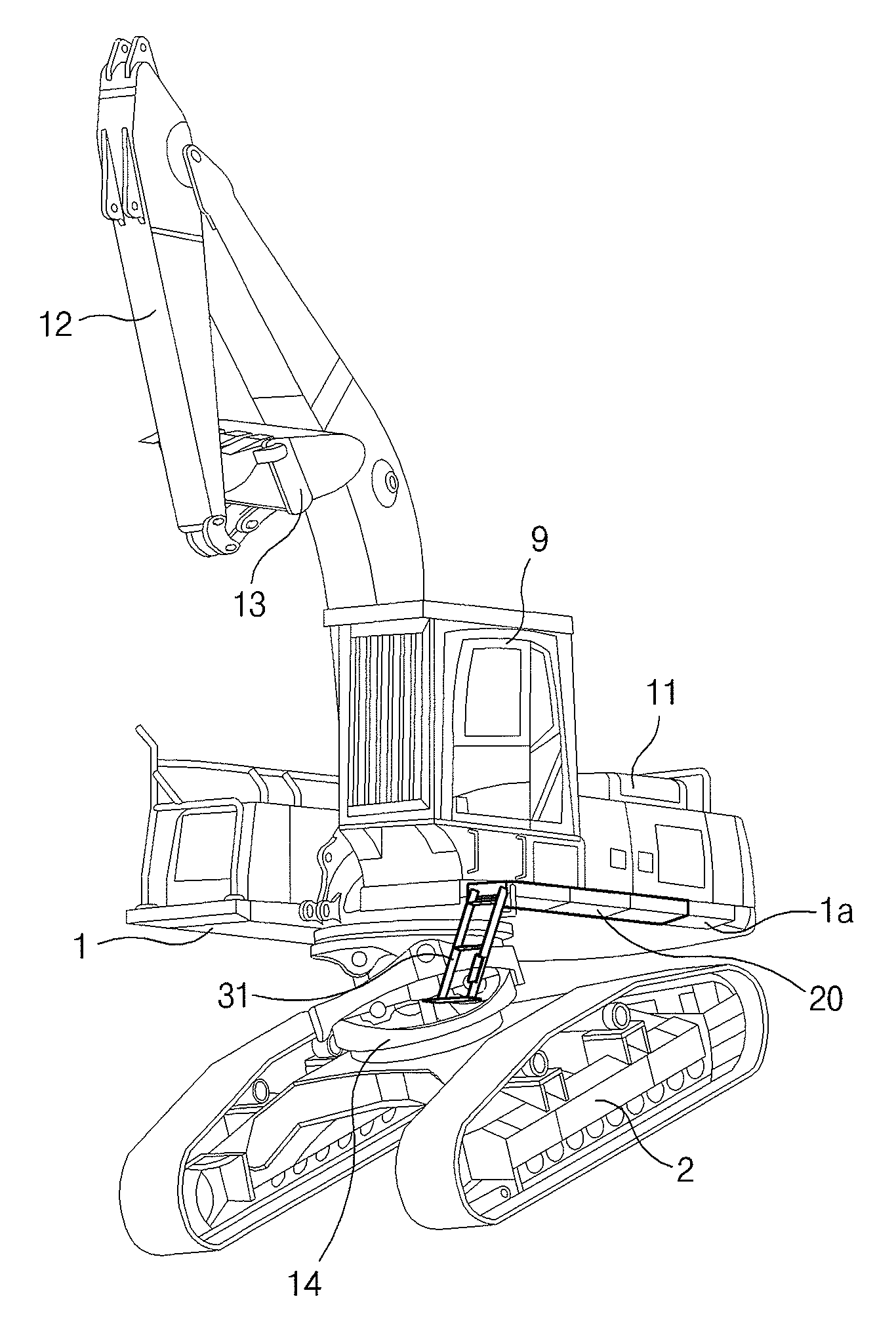
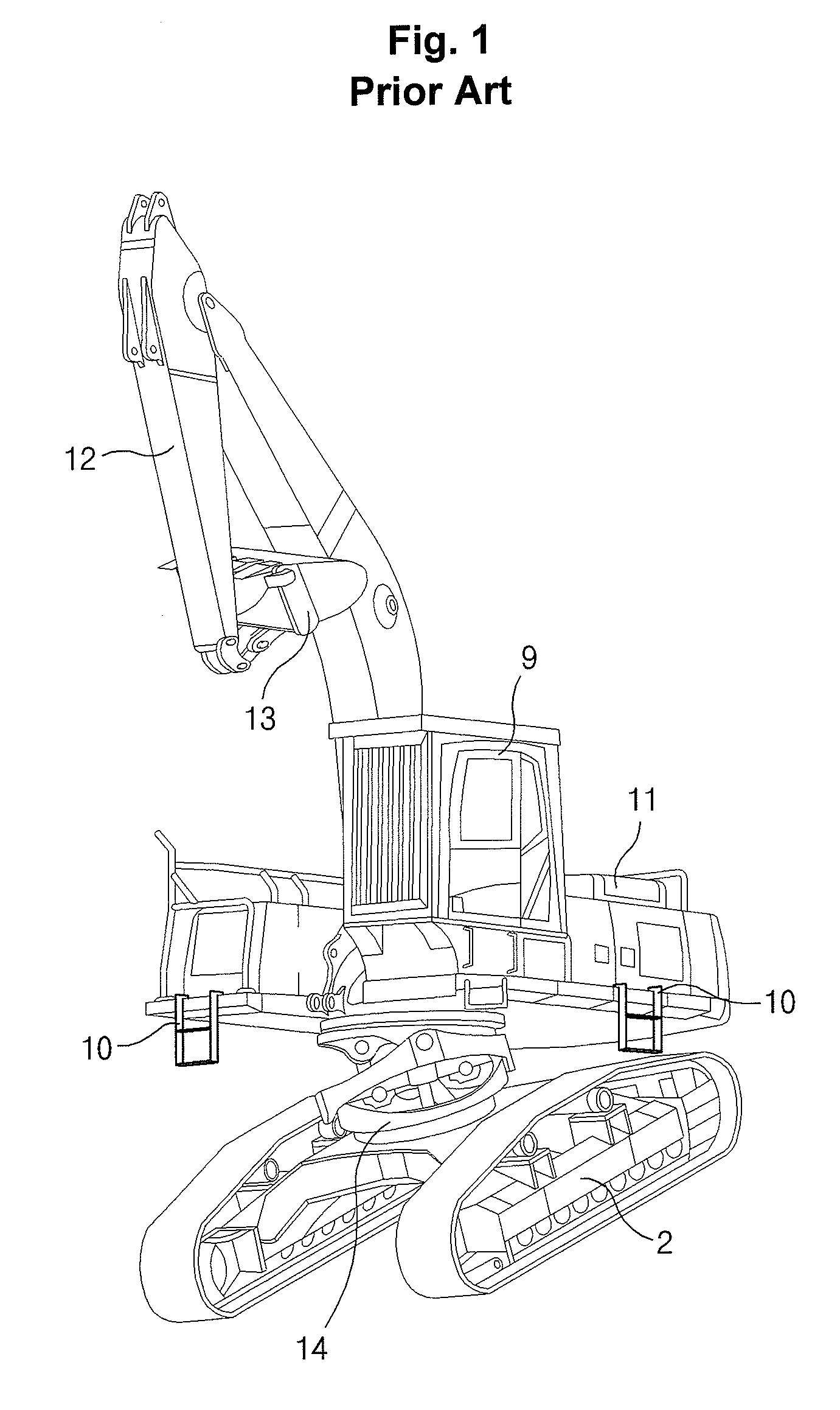
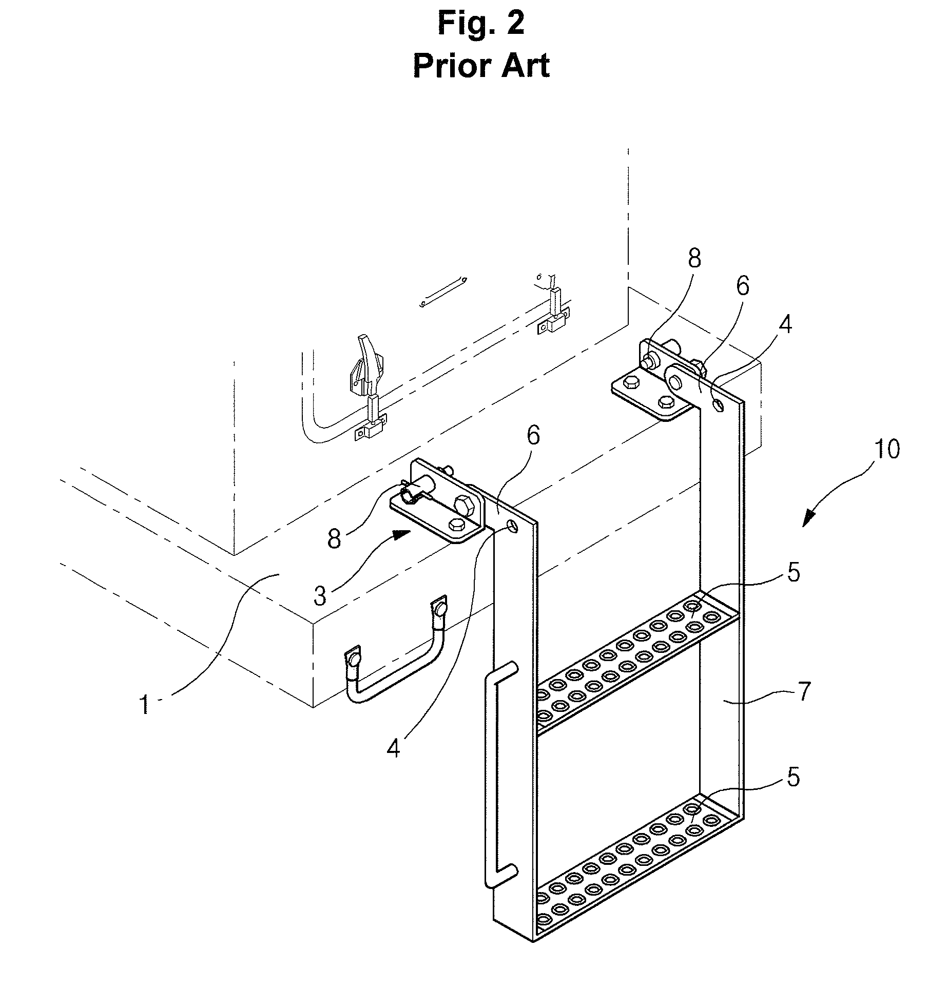
[0068]FIG. 1 is a perspective view illustrating the use state of a conventional fixed step apparatus installed in heavy construction equipment and tree harvester having a leveling system, FIG. 2 is a schematic perspective view of a conventional fixed step apparatus. FIG. 3 is an exploded perspective view of a step apparatus for heavy construction equipment and tree harvester having a leveling system, in which a step frame is folded inside a step protector, according to an embodiment of the present invent...


PUM


Abstract

A step apparatus for heavy construction equipment and tree harvester having a leveling system for controlling a horizontal level of a cab and an upper frame is provided, which includes a step protector including a main body fixedly installed on one side of an upper frame, a step guide hole opened from an inside of the main body to an outside, a guide rail formed along a length direction of an inner side wall of the main body, and an insert hole formed on one side of the guide rail and open toward a vertically upward direction of the guide rail; a side step including a plurality of foot steps arranged at specified intervals on a step frame to form stairs, a step drawer formed on an upper part of the step frame and seated in the step guide hole, and a guide pin positioned adjacent to the step drawer and projected toward the side wall of the main body, wherein when the guide pin is slid along the guide rail, the step frame is seated in the main body or is drawn out from the inside of the main body; and a folding actuator including a cylinder rod coupled to the step drawer to be extended and contracted, the folding actuator drawing the step drawer to the inside of the main body of the step protector.

Description

CROSS-REFERENCE TO RELATED APPLICATION[0001]This application is based on and claims priority from Korean Patent Application No. 10-2008-0048976 and 10-2008-0052641, filed on May 27, 2008 and Jun. 4, 2008, respectively in the Korean Intellectual Property Office, the disclosure of which is incorporated herein in its entirety by reference.BACKGROUND OF THE INVENTION[0002]1. Field of the Invention[0003]The present invention relates to a step apparatus for heavy construction equipment and tree harvester having a leveling system, and more particularly to a step apparatus for heavy construction equipment and tree harvester having an improved leveling system, which can prevent a collision with an external obstacle or a lower driving structure by making the step apparatus in a step protector drawn out and seated in foldable steps even if an upper swing structure is tilted in an inclined workplace or is in a tilted state against the lower driving structure through operation of the leveling sy...

Claims


Application Information

Patent Timeline
Patent Type & Authority Applications(United States)
IPC IPC(8): E06C5/00
CPCB60R3/02E02F9/00E06C5/08E02F9/24E02F9/0833
Inventor KIM, IN WOOPARK, YOUNG OK
Owner VOLVO CONSTR EQUIP
Why Eureka
Try Eureka