Fence system

a technology of fencing and wire cutters, applied in the field of fences, can solve the problems of easy breach of chain link fences by wire cutters, potential liability for users of expanded metal, and compromise of the integrity of the whole fen

Active Publication Date: 2011-01-11
GUARDIAR USA LLC
View PDF34 Cites 29 Cited by
  • Summary
  • Abstract
  • Description
  • Claims
  • Application Information

AI Technical Summary

Benefits of technology

In another embodiment of the invention, two or more vertically-spaced rails extend substantially horizontally across the at least one support member, and two or more horizontally-spaced union strips extend substantially vertically across the rai

Problems solved by technology

A chain link fence, however, is easy to breach with wire cutters.
For example, if one wire of a chain link fence is cut, the integrity of the whole fence is compromised, since chain link is a continuous piece of fabric.
However, such heavier fencing material is only manufactured in standard widths, and thus requires that fence posts be spaced apart at very precise intervals, to match the width of the fencing material, so that the heavier fencing material will properly span between the posts.
This problem is particularly acute when one fencing material (e.g., chain link) that has been hung between p

Method used


Image

  • Fence system
  • Fence system
  • Fence system

Examples


embodiment 1500

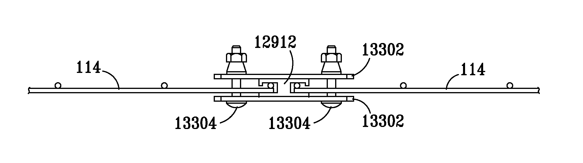
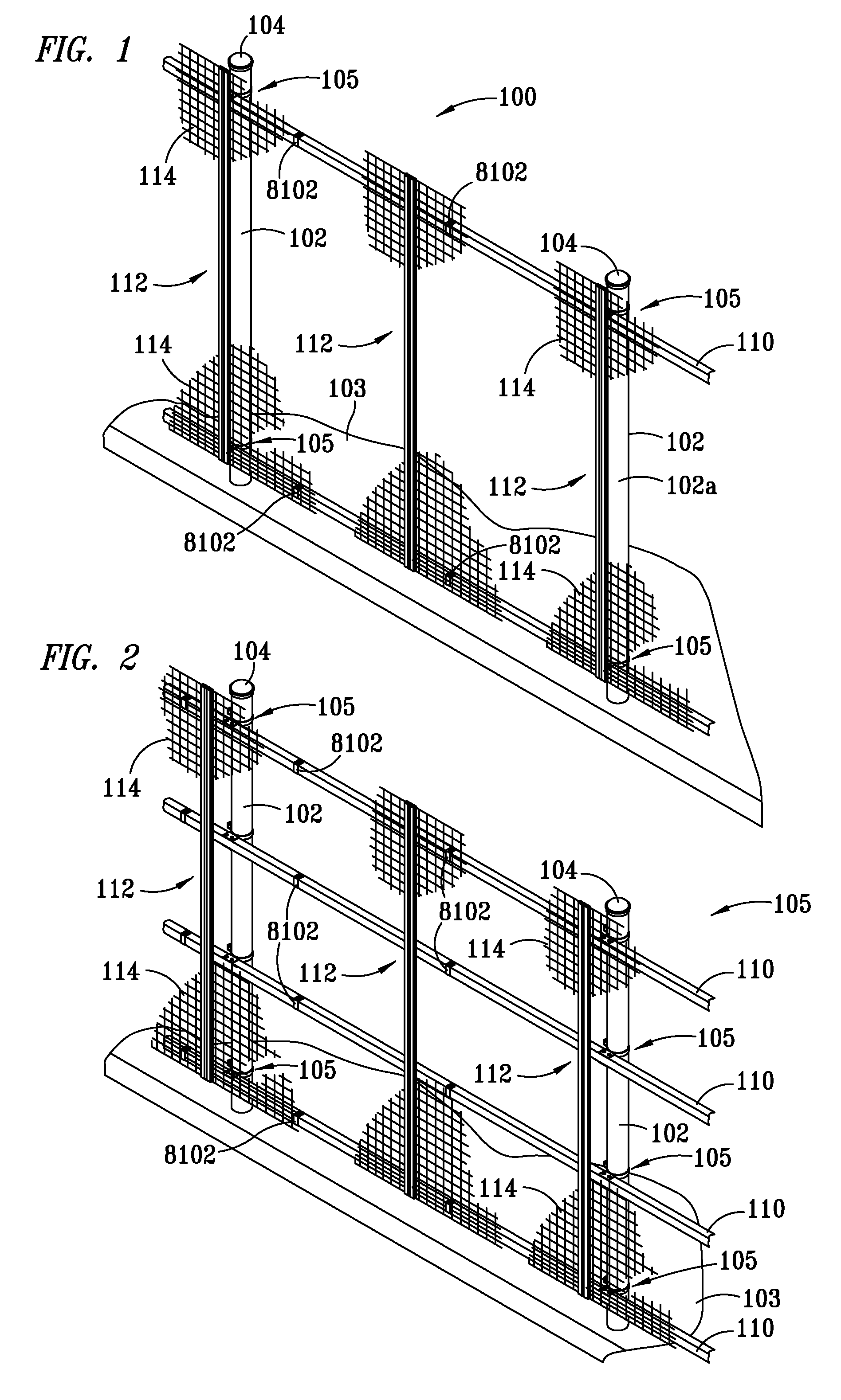
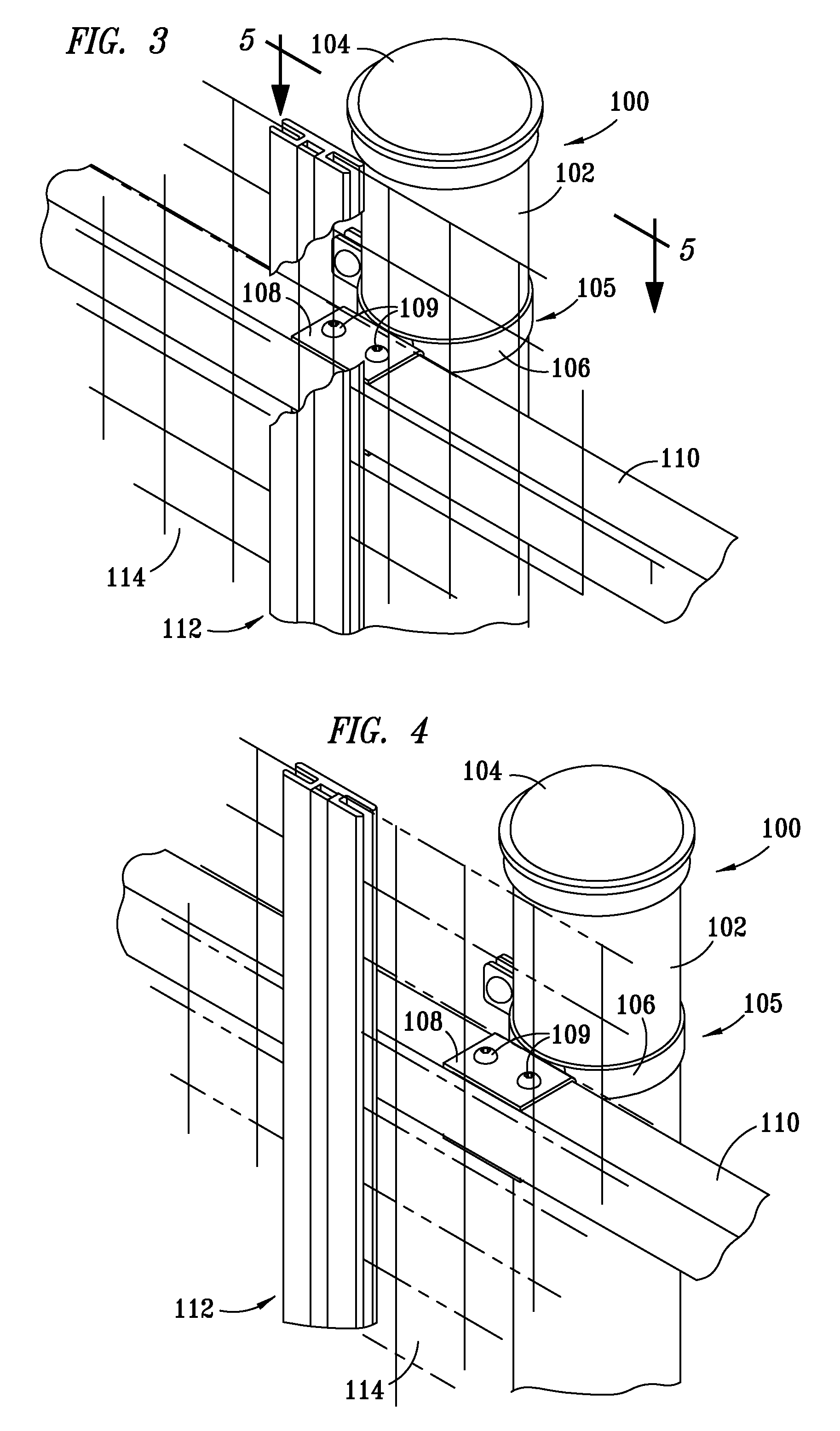
FIG. 15 presents an alternative embodiment 1500 of the present invention wherein rails 110, union strips 112, and infill material 114, such as wire mesh, is secured to two sides of a fence system, to thereby provide additional security. It may be appreciated that the rails 110, union strips 112, and wire mesh 114 may be different on each side, as desired.

embodiment 1600

FIG. 16 presents an alternative embodiment 1600 of the present invention wherein barbed wire, such as Constantina (also known as concertina) wire (i.e., barbed wire that is extended in a spiral for use as a barrier), is positioned atop the fence system of FIG. 15, to thereby provide still further security.

FIG. 17 depicts a bolt (or screw) 1700 preferably having a carriage type of head 1702 (i.e., a “dome-shaped” head with no driver slot) and square shoulder 1703, and configured for receiving a nut 1704, adapted for use in the present invention. The nut 1704 preferably comprises a main portion 1704a having a conical type head, and a breakaway portion 1704b configured for breaking away from the main portion 1704a upon the application of a predetermined amount of torque, thereby rendering the main portion 1704a on the bolt 1700 not readily removable, thereby enhancing security still further.

FIG. 18 depicts a bolt (or screw) 1800 similar to the bolt (or screw) 1700, but for having a pan...


PUM


Abstract

A fence system, and method for making same, includes at least one support member, and at least one infill material having an edge. At least one union strip is coupled to the at least one support member, the at least one union strip including at least one channel configured for receiving the edge of the at least one infill material. In one embodiment of the invention, the at least one channel is U-shaped, and the edge is configured in a U-shape for matingly engaging the at least one U-shaped channel.

Description

TECHNICAL FIELDThe invention relates generally to fences and, more particularly, to fences adapted to architectural applications, trellises, and / or to provide high security.BACKGROUNDFences are well known in the art for providing security to property. Typically, a fence includes a series of posts set in ground, cement, a concrete slab, or the like, with a fencing infill material spanning between or across the posts. A common type of fencing infill material is chain link. A chain link fence, however, is easy to breach with wire cutters. For example, if one wire of a chain link fence is cut, the integrity of the whole fence is compromised, since chain link is a continuous piece of fabric. It may be appreciated that cutting a wire of chain link fence is analogous to cutting a link of chain, wherein the tension on the complete fence or chain is lost. Once the wire is cut, an opening in the fence may then be readily formed through which a person may readily pass with appropriated goods.F...

Claims


Application Information

Patent Timeline
IPC IPC(8): E04H17/16
CPCE04H17/161E04H17/168E04H17/24Y10T29/49948E04H17/1602E04H17/1447E04H17/009E04H17/21E04H17/1417
Inventor PAYNE, JOHN F.
Owner GUARDIAR USA LLC
Why Eureka
Try Eureka