Priming module for microfluidic chips

a microfluidic chip and priming technology, applied in the field of systems and methods, can solve the problems of reducing the affecting the testing of chemical or biological samples using the chip, and erroneous analysis performed using the chip, so as to reduce the amount of time required for a priming process. , the effect of efficient priming

Active Publication Date: 2011-01-11
CAPLIPER LIFE SCI INC
View PDF45 Cites 103 Cited by
  • Summary
  • Abstract
  • Description
  • Claims
  • Application Information

AI Technical Summary

Benefits of technology

[0014]The use of a priming unit which has an adapter portion that is separable from the remainder of the priming unit enables a variety of different adapter portions to be used as a part of the priming unit. As each adapter portion supports a particular chip type or chip configuration, the use of multiple adapter portions allows for efficient priming, as a single priming unit to be used to prime, e.g., pressurize, differently configured chips for testing. Some adapters are arranged with manifolds, or interconnected channels and cavities, which enable multiple wells and capillaries of a chip to be pressurized at substantially the same time, thereby at least partially reducing the amount of time required for a priming process to occur.

Problems solved by technology

The presence of air bubbles in matrix mixtures in a chip may adversely affect the testing of chemical or biological samples using the chip.
The priming of a chip, if performed inaccurately or incorrectly, may cause an analysis performed using the chip to be erroneous and, hence, unreliable.
Further, if a test on a minute sample of material is incorrectly performed, repeating the test may be difficult, as there may not be enough of a material sample available to perform a new test.
However, priming only one well at a time is inefficient when the priming of more than one well is desired.
Hence, if chips of more than one configuration are to be tested, then multiple priming stations may be required, which is costly and inefficient.

Method used


Image

  • Priming module for microfluidic chips
  • Priming module for microfluidic chips
  • Priming module for microfluidic chips

Examples


Embodiment Construction

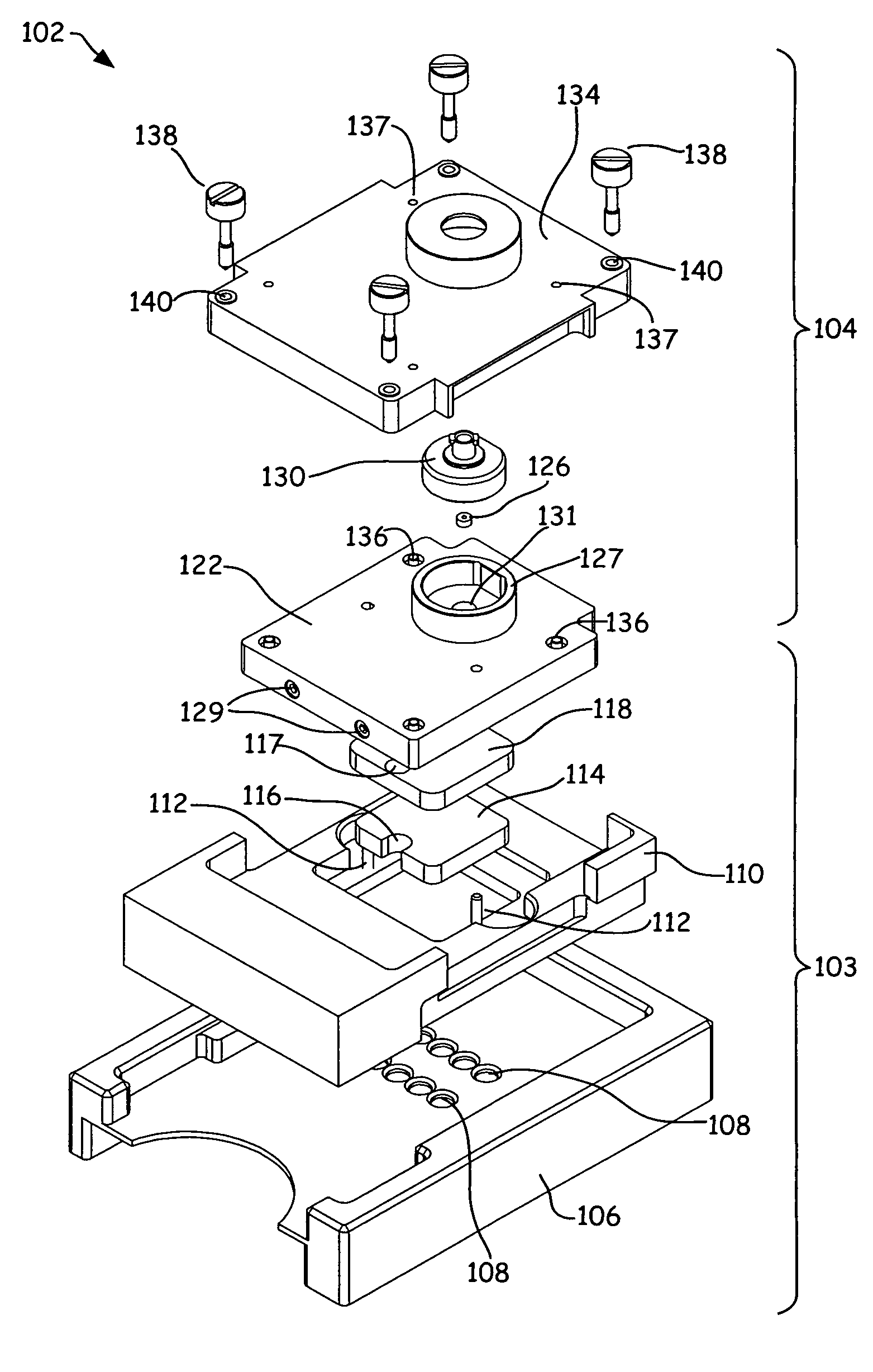
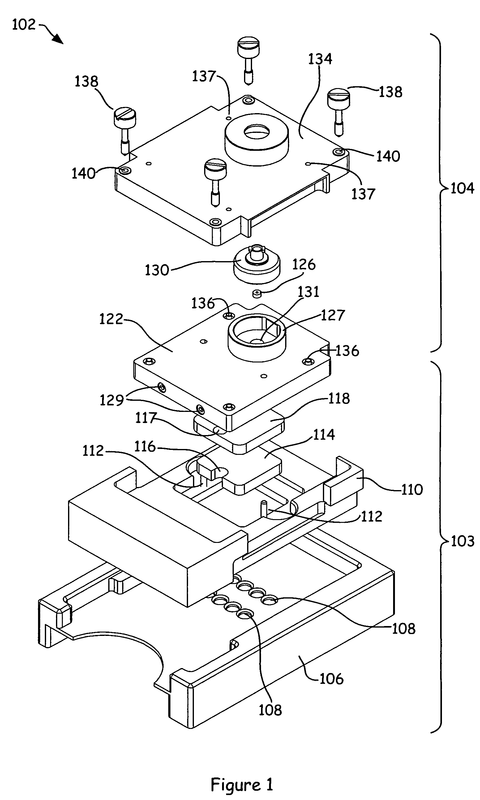
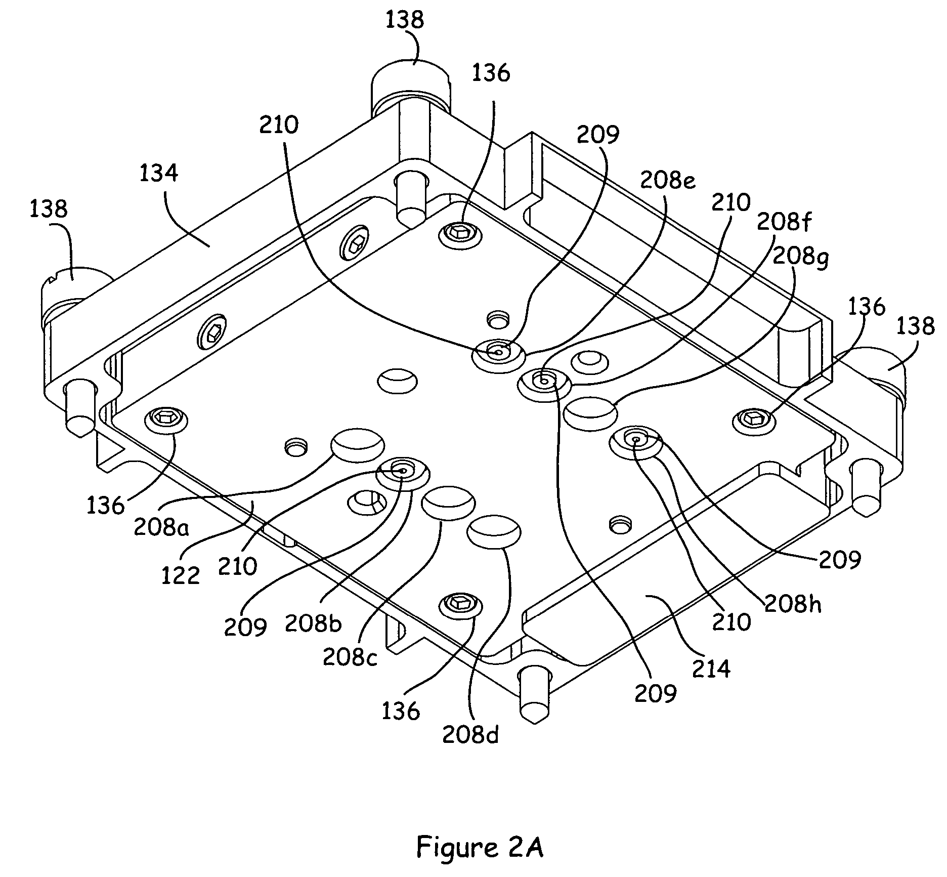
[0026]By designing a priming station to accommodate more than one chip or sample substrate configuration, the priming station may be used more efficiently. For example, parts of a priming station designed to support and position a chip may be suitable for use by chips of a variety of different configurations, while an adapter module of the chip may be varied as needed for different chips. The adapter module may be arranged to be readily swapped into and out of the overall priming station. Permitting components of a priming station to remain essentially “constant,” while exchanging adapter modules, may substantially maximize the use of the constant components. In other words, enabling a priming station to take on different “personalities,” e.g., have different configurations, through the use of adapters allows a priming station to be used efficiently.

[0027]A priming station with adapter, or “personality,” modules may be configured to fill, or pressurize, more than one well or channel...


PUM

PropertyMeasurementUnit
sizeaaaaaaaaaa
sizeaaaaaaaaaa
sizeaaaaaaaaaa

Abstract

Methods and apparatuses for priming sample substrates such as DNA sipper chips are disclosed. According to one aspect of the present invention, a priming system that is suitable for priming a substrate which has a plurality of wells and at least one channel includes a base unit and a top unit. The base unit is arranged to accommodate, or support, the substrate. The top unit, which is substantially physically separate from the base unit, fits over the substrate when the substrate is held by the base unit. The top unit includes an adapter portion that interfaces with the substrate. Included in the adapter portion is a first cavity that is used to facilitate pressurizing a first well of the substrate when the adapter portion is interfaced with the substrate such that the first cavity is aligned with the first well.

Description

CROSS REFERENCE TO RELATED APPLICATION[0001]This application is a continuation of U.S. application Ser. No. 10 / 084,245, filed Feb. 27, 2002, now abandoned, which claims benefit to U.S. Provisional Patent Application No. 60 / 273,001, filed Mar. 2, 2001, which is incorporated herein by reference in its entirety for all purposes.BACKGROUND OF THE INVENTION[0002]1. Field of Invention[0003]The present invention relates generally to systems and methods for performing chemical and biological analyses. More particularly, the present invention relates to a priming module with an adapter that enables a single priming module to be used for priming a variety of both single channel and multiple channel microfluidic chips.[0004]2. Description of the Related Art[0005]Microfluidic analytical techniques are often used in chemical and biological testing because of advantages such as the ability to employ small sample sizes. Microfluidic analysis generally involves the movement of minute quantities of ...

Claims


Application Information

Patent Timeline
Patent Type & Authority Patents(United States)
IPC IPC(8): G01N1/10B01L3/00B01L9/00B01L99/00C12M1/34C12Q1/68
CPCB01L3/0293B01L9/527B01L3/5027Y10T436/2575B01L2200/027B01L2400/0487B01L2200/023
Inventor KENNEDY, MICHAEL J.GEFTER, ALEXANDER A.
Owner CAPLIPER LIFE SCI INC
Why Eureka
Try Eureka