Method and device for determining a distance from an object

a distance measurement and distance technology, applied in distance measurement, height/levelling measurement, instruments, etc., can solve the problems of destroying the light receiver, unable to reliably determine the distance at an excessively high reception signal power, and unable to distinguish the reception signal from unavoidable interference, etc., to achieve the effect of optimizing the measuring range and extending the measuring rang

a distance measurement and distance technology, applied in distance measurement, height/levelling measurement, instruments, etc., can solve the problems of destroying the light receiver, unable to reliably determine the distance at an excessively high reception signal power, and unable to distinguish the reception signal from unavoidable interference, etc., to achieve the effect of optimizing the measuring range and extending the measuring rang

US7869005B2Active Publication Date: 2011-01-11FARO TECH INC

Image

  • Method and device for determining a distance from an object
  • Method and device for determining a distance from an object
  • Method and device for determining a distance from an object

Examples


Embodiment Construction

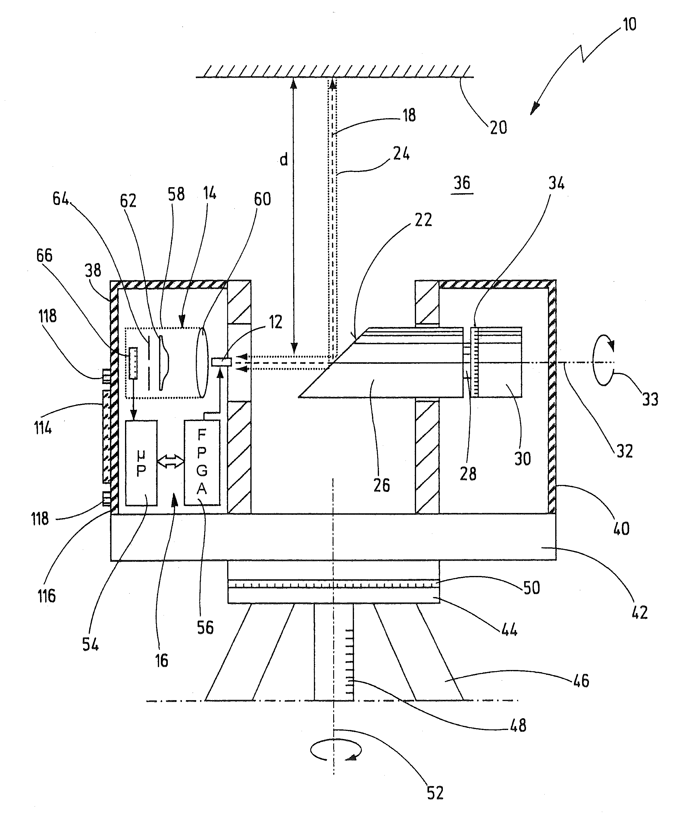
[0049]In FIG. 1, a laser scanner is designated in its entirety by the reference numeral 10. The laser scanner 10 is one possible embodiment of a device according to the present invention. However, the novel device can also be a simple distance measuring device which measures one-dimensionally and which determines the distance from an object with the aid of a emission light beam and a reception light beam. The invention is also not restricted to the use of light beams in the narrower sense (wavelengths between 300 and 1000 nm), but rather can in principle also be realized with electromagnetic waves from a different wavelength range as long as a quasi-optical propagation is present. The expression light beam as used here therefore encompasses such electromagnetic waves as well.

[0050]The laser scanner 10 comprises a light emitter 12 and a light receiver 14, which are connected to an evaluation and control unit 16. In the preferred exemplary embodiment, the light emitter 12 comprises a ...


PUM


Abstract

A device for determining a distance from an object may include a light emitter for emitting an emission light beam, a light receiver for receiving a reception light beam, and an evaluation unit for determining the distance on the basis of a propagation time of the emission and reception light beams. The reception light beam may arise as a result of reflection of the emission light beam at the object. The light receiver may have a reception optical unit comprising a first lens element and a pinhole diaphragm. A light-impermeable element may shade a central region of the reception optical unit in such a way that the reception light beam is incident in the form of a light ring on the pinhole diaphragm. A second lens element, which is substantially hat-shaped in cross section, is arranged between the first lens element and the pinhole diaphragm.

Description

CROSS REFERENCE TO RELATED APPLICATIONS[0001]This is a Continuation Application of International Application No. PCT / EP2009 / 050888, filed on Jan. 27, 2009 priority to which is claimed under 35 U.S.C. §120. Priority under 35 U.S.C. §119(a) and 35 U.S.C. §365(b) is also claimed from German Application Nos. 10 2008 008 063.2, filed Feb. 1, 2008; and 10 2008 014 275.1, filed Mar. 3, 2008, the disclosures of which are also incorporated herein by reference.FIELD OF INVENTION[0002]The present invention relates to a device for determining a distance from an object.BACKGROUND[0003]Such a device is known in principle from DE 20 2006 005 643 U1, although this document does not disclose any details of a reception optical unit. The applicant of the present application has, however, already sold devices as described in DE 20 2006 005 643 U1 including a reception optical unit comprising a pinhole diaphragm and a lens element, under the product designation LS 840 / 880.[0004]The known device, known a...

Claims


Application Information

Patent Timeline
11 Jan 2011
Publication
US7869005B2
IPC
G01C3/08
CPC
G01C15/002; G01S7/4812; G01S7/4817; G01S17/36; G01S17/42
Inventors
OSSIG, MARTIN; SCHUMANN, PHILIPP