Reactance filter having an improved edge steepness

a filter and steepness technology, applied in piezoelectric/electrostrictive/magnetostrictive devices, piezoelectric/electrostriction/magnetostriction machines, electrical apparatus, etc., can solve the problem of filter center of passband, filter is strongly reduced, filter cannot meet possible selection demands, etc. problem, to achieve the effect of improving the steepness, reducing the selection level, and sufficient bandwidth

Inactive Publication Date: 2006-10-24
SNAPTRACK
View PDF4 Cites 13 Cited by
  • Summary
  • Abstract
  • Description
  • Claims
  • Application Information

AI Technical Summary

Benefits of technology

[0015]The object of the present invention is therefore to provide a reactance filter constructed from BAW resonators that has an improved edge steepness with sufficient bandwidth, without having to accept an additional matching or a reduction of the selection level for this purpose.

Problems solved by technology

If it is now attempted, in such a steep-edged filter, to increase the bandwidth to the level of the filter having the larger capacitance ratio by increasing the center frequencies of series resonators and / or reducing the center frequency of the parallel resonators, a strong mismatching results in the center of the passband, because now faprs.
However, with this measure the selection level of the BAW reactance filter is strongly reduced, so that the filter can no longer meet possible selection demands, and can for example no longer sufficiently attenuate undesired frequencies.

Method used


Image

  • Reactance filter having an improved edge steepness
  • Reactance filter having an improved edge steepness
  • Reactance filter having an improved edge steepness

Examples


first exemplary embodiment

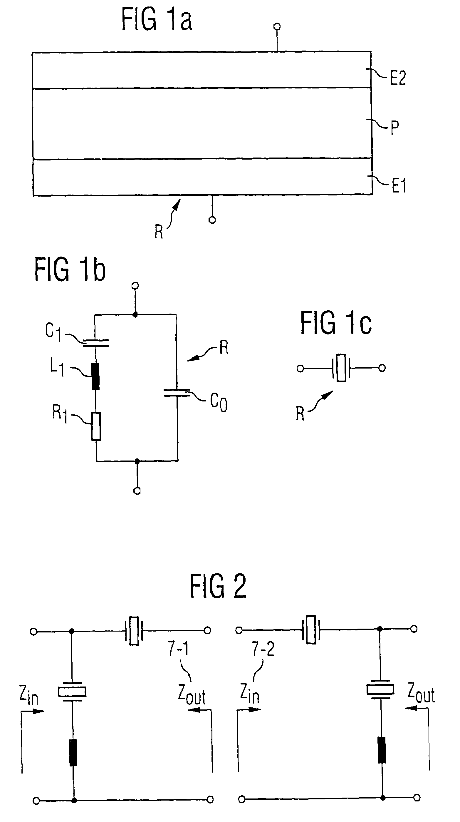
[0051]Resonators constructed as in FIG. 1a are wired together to form a reactance filter (see FIG. 1b). Each resonator comprises a first electrode layer E1, a piezoelectric layer P and a second electrode layer E2 (FIG. 1a). In FIG. 1c, the symbol standardly used for resonators is shown.

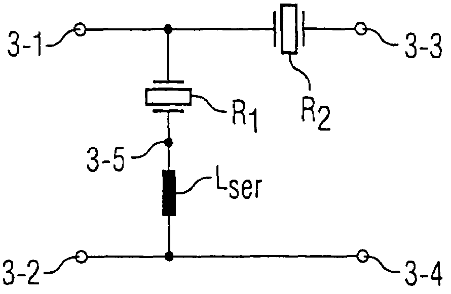
[0052]FIG. 7 shows a basic element constructed from a first resonator R1 in a parallel branch and a second resonator R2 in a serial branch. Terminals 3-1 and 3-2 form the input of the filter, and terminals 3-3 and 3-4 form the output of the filter. The parallel branch, or resonator R1 in the parallel branch, is connected with terminals 3-2 or 3-4 via a series inductance Lser, formed from the sum of the inductances of the connection to the housing ground. According to the present invention, in this exemplary embodiment resonator R1 is formed with a piezoelectric layer P made of zinc oxide, which has an electromechanical coupling constant K2eff 1, and resonator R2 is formed with a piezoelectric layer P ...

second exemplary embodiment

[0054]Again, a reactance filter is constructed having a basic element wired according to FIG. 2, and both resonators are fashioned as in FIG. 1. In contrast to the first exemplary embodiment, both resonators do comprise the same piezoelectric material for the layer P, but differ in the electrode material used for electrodes E1 and E2. While aluminum is used for resonators R1, tungsten is used as the electrode material for resonators R2. Because k2eff 2>k2eff 1 holds for the effective coupling k2eff, as a result a reactance filter is obtained whose passband curve 2 is shown in FIG. 11. It can be seen that curve 2 of the filter according to the present invention has a left edge that is set significantly steeper than the left edge of curve 1, which shows the passband response of a known reactance filter in which the same electrode material (tungsten) was used for both resonators.

[0055]FIG. 12 shows the influence of the electrode material on the impedance characteristic of a resonator. ...

third exemplary embodiment

[0056]A resonator is formed according to FIG. 13. This resonator comprises, between a first electrode E1 and a second electrode E2, made for example of aluminum, a piezoelectric layer P made for example of aluminum nitride, as well as a dielectric layer D, made for example of silicon oxide. If the layer portion of the silicon oxide layer is 16%, the coupling coefficient k2eff decreases from a value of 0.0645, determined in a resonator according to FIG. 1 having aluminum nitride as a piezoelectric layer, to a value of 0.057 for the resonator according to the present invention, as shown in FIG. 13. This latter resonator therefore has a smaller distance between the resonance and the anti-resonance frequency, and can be used in combination with conventional resonators (see FIG. 1), whereby in the reactance filter (for example according to FIG. 7) the serial and parallel resonators are formed differently, i.e., respectively according to FIG. 1 or FIG. 13.


PUM


Abstract

A reactance filter, which is constructed from BAW resonators, has at least one basic element that has a first resonator in a first branch and a second resonator in a second branch. In one branch, there is situated a resonator having a greater ratio of dynamic to static capacitance than in the second branch, so that a filter is obtained having a resulting passband in which one edge is set steeper than the other edge. The selection of the edge that is to be set steeply takes place through the allocation of the first branch to the serial or to the parallel branch.

Description

BACKGROUND OF THE INVENTION[0001]The present invention relates to bulk acoustic wave filters (also known as BAW filters) that are constructed according to the reactance filter principle.[0002]From an article by K. M. Lakin et al. in Microwave Symposium Digest, IEEE MTT-S International 1995, pp. 883–886, it is known to construct reactance filters from BAW resonators. Here, these resonators are used as impedance elements, and are for example wired or connected to form ladder-type or lattice filters. This type of wiring for the manufacture of filters is also known as branching technology.[0003]According to FIG. 1a, in its simplest specific embodiment a BAW resonator R is made up of a thin film P of a piezoelectric material, which is provided with an electrode E1, E2 on its upper and lower side respectively. Ideally, this structure is surrounded by air on both electrode sides. When an electrical voltage is applied to the electrodes, an electrical field acts on the piezoelectric layer, w...

Claims


Application Information

Patent Timeline
Patent Type & Authority Patents(United States)
IPC IPC(8): H03H9/58H01L41/107H03H9/54H03H9/60H03H9/70
CPCH03H9/605
Inventor UNTERBERGER, MICHAEL
Owner SNAPTRACK
Why Eureka
Try Eureka