Multiplexer, high-frequency front end circuit, and communication device

a high-frequency front end circuit and multi-channel technology, applied in the direction of low-noise amplifiers, amplifiers, semiconductor devices/discharge tubes, etc., can solve the problems of difficult to demultiplex or multiplex a high-frequency signal of a wide frequency band, and difficult to obtain flat bandpass characteristics. , to achieve the effect of reducing or preventing the loss of the pass band of the first filter, improving the demultiplexing

a high-frequency front end circuit and multi-channel technology, applied in the direction of low-noise amplifiers, amplifiers, semiconductor devices/discharge tubes, etc., can solve the problems of difficult to demultiplex or multiplex a high-frequency signal of a wide frequency band, and difficult to obtain flat bandpass characteristics. , to achieve the effect of reducing or preventing the loss of the pass band of the first filter, improving the demultiplexing

US20200014370A1Active Publication Date: 2020-01-09MURATA MFG CO LTD

Image

  • Multiplexer, high-frequency front end circuit, and communication device
  • Multiplexer, high-frequency front end circuit, and communication device
  • Multiplexer, high-frequency front end circuit, and communication device

Examples


first preferred embodiment

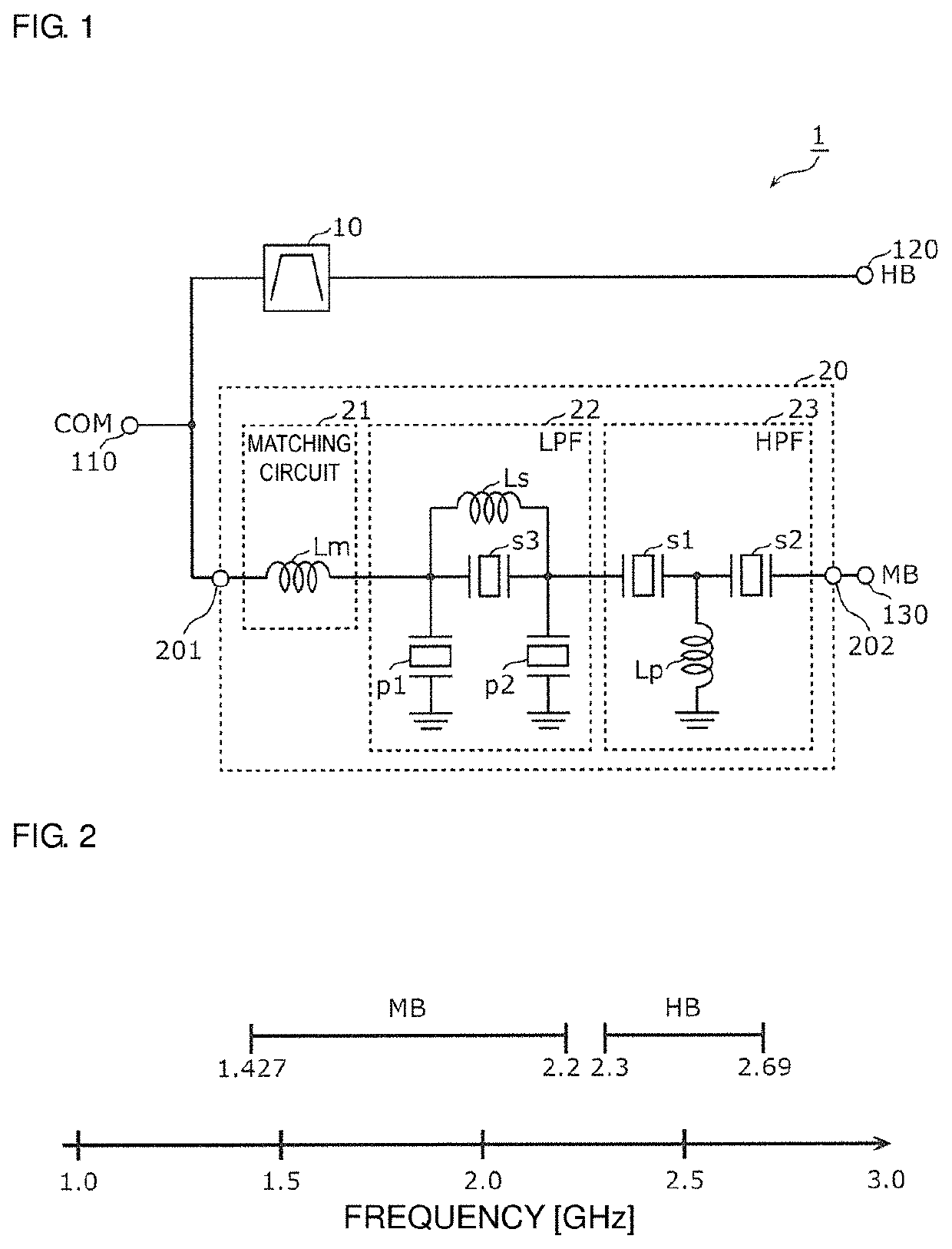
[0067]FIG. 1 is a circuit block diagram of a hybrid multiplexer according to a first preferred embodiment of the present invention. FIG. 2 is a diagram illustrating frequency bands supported by the hybrid multiplexer 1 according to the first preferred embodiment. Note that in FIG. 1, for a filter 20, a circuit configuration is also illustrated.

[0068]The hybrid multiplexer 1 includes a common terminal 110 (a COM terminal in FIG. 1), a filter 10 which allows a high-frequency signal in a first frequency band to pass therethrough, and the filter 20 which allows a high-frequency signal in a second frequency band to pass therethrough. In the present preferred embodiment, a frequency at a low-band end of the first frequency band is located on a higher-band side than a frequency at a high-band end of the second frequency band. Specifically, as illustrated in FIG. 2, the first frequency band is preferably, for example, a high band (about 2300 MHz-about 2690 MHz: hereinafter, referred to as a...

second preferred embodiment

[0173]The hybrid multiplexer described above may preferably be used in, for example, a high-frequency module defining an LTE capable high-frequency front end circuit, for example. In the present preferred embodiment, such a high-frequency module will be described.

[0174]FIG. 16 is a circuit block diagram illustrating a configuration of a high-frequency module 2 according to a second preferred embodiment of the present invention. Note that FIG. 16 also illustrates a peripheral configuration connected to the high-frequency module 2. The peripheral configuration includes an antenna element ANT, an RFIC (Radio Frequency Integrated Circuit) 3 defining an RF signal processing circuit to process a high-frequency signal, and a BBIC (Baseband Integrated Circuit) 4 defining a baseband signal processing circuit. The high-frequency module 2, the RFIC 3, and the BBIC 4 define a communication device 5.

[0175]The high-frequency module 2 transmits, for example, a high-frequency signal having a Band (...


PUM


Abstract

A hybrid multiplexer includes a filter configured to allow a high-frequency signal of an HB to pass therethrough, and a filter configured to allow a high-frequency signal of an MB to pass therethrough, in which the filter includes a matching circuit, a first resonance circuit defined by one of an LPF and an HPF, and a second resonance circuit defined by the other of the LPF and the HPF, the LPF includes an inductor and a parallel arm resonator, the HPF includes a serial arm resonator and an inductor, and a resonant frequency of the parallel arm resonator and an anti-resonant frequency of the serial arm resonator are both located between a frequency at a low-band end of the HB and a frequency at a high-band end of the HB.

Description

CROSS REFERENCE TO RELATED APPLICATIONS[0001]This application claims the benefit of priority to Japanese Patent Application No. 2017-072760 filed on Mar. 31, 2017 and is a Continuation Application of PCT Application No. PCT / JP2018 / 010643 filed on Mar. 16, 2018. The entire contents of each application are hereby incorporated herein by reference.BACKGROUND OF THE INVENTION1. Field of the Invention[0002]The present invention relates to a multiplexer, and a high-frequency front end circuit including the same, and a communication device.2. Description of the Related Art[0003]As a multiplexer in which one terminal of each of a plurality of filters is commonly connected, an existing diplexer configured of a high pass filter which is an LC filter including an LC parallel resonance circuit and a low pass filter which is an LC filter including an LC parallel resonance circuit has been disclosed (see, for example, Japanese Unexamined Patent Application Publication No. 2006-128881).[0004]Here, ...

Claims


Application Information

Patent Timeline
09 Jan 2020
Publication
US20200014370A1
IPC
H03H9/70; H03H7/38; H03H9/60; H03H9/54; H03F3/195
CPC
H03F2200/451; H03F2200/294; H04B1/52; H03H7/38; H03H9/542; H03F3/195; H03H9/70; H03H9/605
Inventors
MATSUBARA, HIROSHI; KATO, MASANORI