Acoustic wave filter device

a filter device and waveguide technology, applied in the direction of impedence networks, electrical devices, etc., can solve the problems of increasing loss in the passband, and achieve the effects of reducing the loss of insertion in the passband, increasing the steepness of the filter characteristic, and small electromechanical coupling coefficien

Active Publication Date: 2012-08-14
MURATA MFG CO LTD
View PDF19 Cites 13 Cited by
  • Summary
  • Abstract
  • Description
  • Claims
  • Application Information

AI Technical Summary

Benefits of technology

[0009]To overcome the problems described above, preferred embodiments of the present invention provide an acoustic wave filter device having a ladder circuit configuration which has outstanding steepness of a filter characteristic and a low loss in a passband.
[0012]The acoustic wave filter device according to the first preferred embodiment of the present invention preferably further includes a piezoelectric substrate made of a piezoelectric monocrystal, and electrodes provided on the piezoelectric substrate. A propagation direction ψ obtained when a crystalline cutting plane of the piezoelectric substrate and an acoustic wave propagation direction are expressed as Euler angles (φ, θ, ψ) is selected so that an electromechanical coupling coefficient of one of the plurality of series arm resonators having the lowest anti-resonant frequency is less than an average of electromechanical coupling coefficients of all of the plurality of series arm resonators. In this case, by setting only an Euler angle ψ as a propagation direction selected as described previously even on the same piezoelectric substrate, an acoustic wave filter device capable of increasing the steepness of a filter characteristic can be provided.
[0014]The acoustic wave filter device according to the second preferred embodiment of the present invention preferably further includes a piezoelectric substrate made of a piezoelectric monocrystal, and electrodes provided on the piezoelectric substrate. A propagation direction ψ obtained when a crystalline cutting plane of the piezoelectric substrate and an acoustic wave propagation direction are expressed as Euler angles (φ, θ, ψ) is selected so that an electromechanical coupling coefficient of one of the plurality of parallel arm resonators having the lowest anti-resonant frequency is less than an average of electromechanical coupling coefficients of all of the plurality of parallel arm resonators. In this case, by setting only an Euler angle ψ as a propagation direction selected as described previously even on the same piezoelectric substrate, an acoustic wave filter device capable of increasing the steepness of a filter characteristic can be provided.
[0016]According to the first preferred embodiment of the present invention, an anti-resonant frequency of at least one of the plurality of series arm resonators is lower than that of remaining ones of the plurality of series arm resonators, and one of the plurality of series arm resonators having a relatively low anti-resonant frequency has a resonant frequency located in a passband and a relatively small electromechanical coupling coefficient k2. Accordingly, it is possible to increase the steepness of a filter characteristic on a higher-frequency side of a passband and reduce an insertion loss in the passband.
[0017]According to the second preferred embodiment of the present invention, a resonant frequency of at least one of the plurality of parallel arm resonators is set to a relatively high frequency, and one of the plurality of parallel arm resonators having the highest resonant frequency has an anti-resonant frequency located in a passband and a relatively small electromechanical coupling coefficient. Accordingly, it is possible to increase the steepness of a filter characteristic on a lower-frequency side of a passband and reduce an insertion loss in the passband.
[0018]According to the first and second preferred embodiments of the present invention, an acoustic wave filter device that is capable of increasing the steepness of a filter characteristic at a boundary between a passband and an attenuation band and achieving a low loss in the passband can be provided.

Problems solved by technology

However, since the anti-resonant frequency of the parallel arm resonator 114 is located at an end portion of the passband, a loss is increased in the passband when the steepness of a filter characteristic is increased on a lower-frequency side of the passband.

Method used


Image

  • Acoustic wave filter device
  • Acoustic wave filter device
  • Acoustic wave filter device

Examples


first preferred embodiment

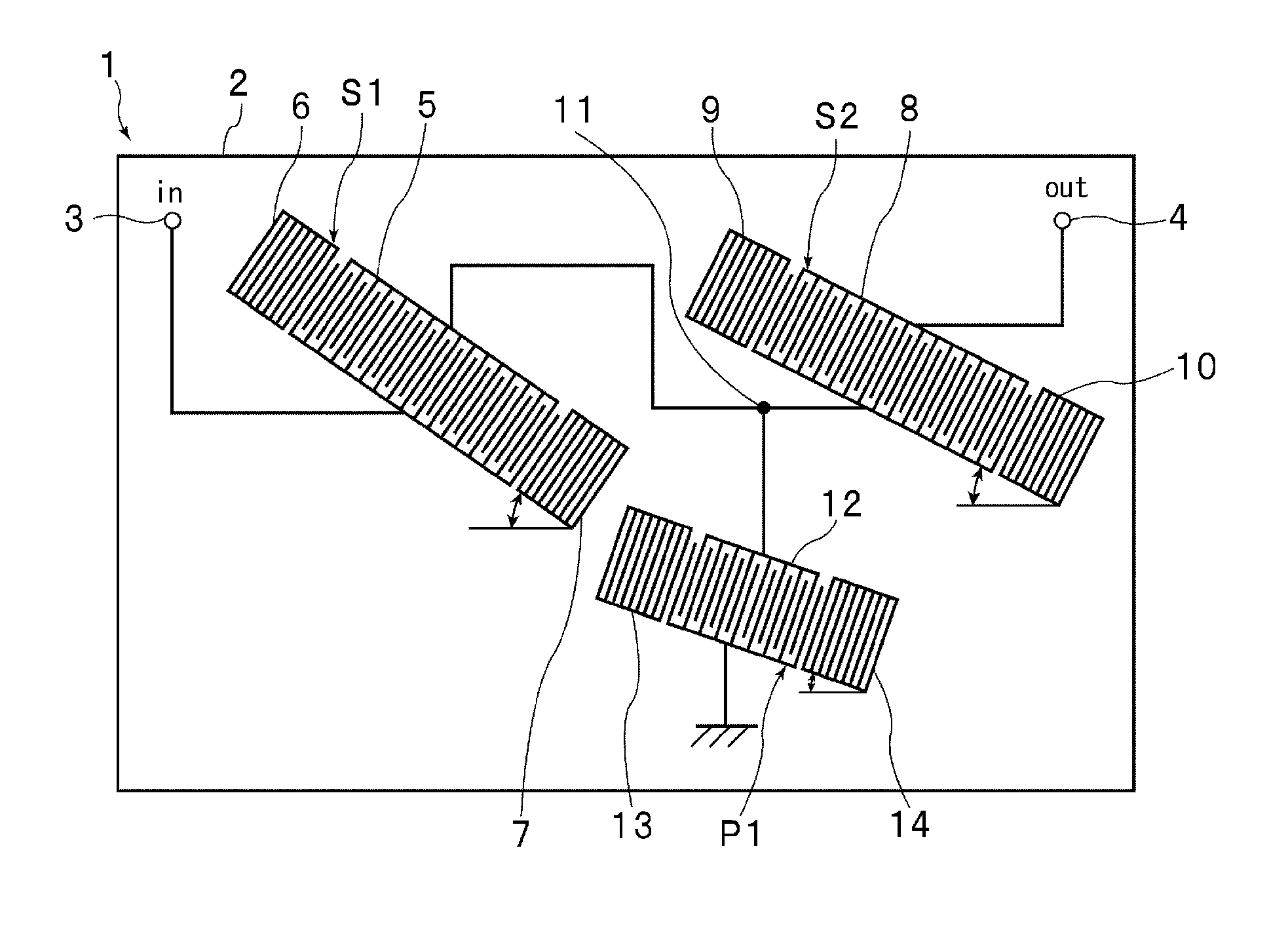
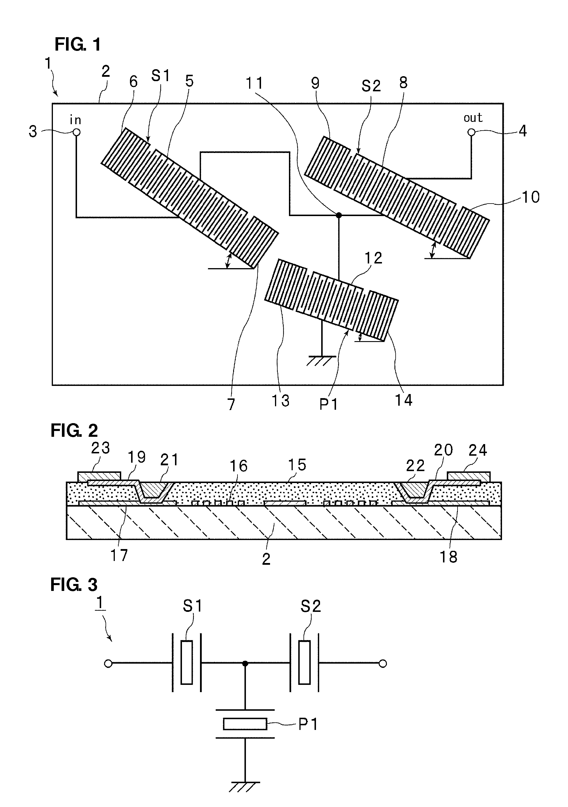
[0035]FIG. 1 is a schematic plan view illustrating an electrode structure of an acoustic wave filter device according to the first preferred embodiment of the present invention. FIG. 2 is a schematic elevational cross-sectional view showing a three-dimensional structure of the acoustic wave filter device. FIG. 3 is a circuit diagram of the acoustic wave filter device.

[0036]As illustrated in FIG. 3, in an acoustic wave filter device 1 according to the present preferred embodiment, a first series arm resonator S1 and a second series arm resonator S2 are connected in series with each other at a series arm connecting an input terminal and an output terminal to each other. A parallel arm resonator P1 is inserted in a parallel arm connected between the series arm and a ground potential. That is, a ladder circuit is defined by two series arm resonators, the first series arm resonator S1 and the second series arm resonator S2, and a single parallel arm resonator, the parallel arm resonator ...

second preferred embodiment

[0073]FIG. 8 is a circuit diagram of an acoustic wave filter device having a ladder circuit configuration according to the second preferred embodiment of the present invention. In this preferred embodiment, the same or substantially the same piezoelectric substrate, the same or substantially the same material for forming an electrode structure, and the same or substantially the same material for forming a dielectric layer as those used in the first preferred embodiment are used, and only a circuit configuration is changed as shown in FIG. 8. That is, an acoustic wave filter device 21 according to the second preferred embodiment includes a first series arm resonator S11, a second series arm resonator S12, a third series arm resonator S13, a fourth series arm resonator S14, a first parallel arm resonator P11, and a second parallel arm resonator P12. The first parallel arm resonator P11 and the second parallel arm resonator P12 are disposed at a first parallel arm and a second parallel...


PUM


Abstract

An acoustic wave filter device is capable of increasing the steepness of a filter characteristic at a boundary between a passband and an attenuation band and achieving a low loss in the passband. The acoustic wave filter device has a ladder circuit configuration including a plurality of series arm resonators and at least one parallel arm resonator. The anti-resonant frequency of the series arm resonator is different from that of the series arm resonator. The series arm resonator having the lowest anti-resonant frequency has a resonant frequency located in the passband and an electromechanical coupling coefficient less than an average of electromechanical coupling coefficients of the series arm resonators.

Description

BACKGROUND OF THE INVENTION[0001]1. Field of the Invention[0002]The present invention relates to acoustic wave filter devices that are used as, for example, bandpass filters for mobile telephones, and, more particularly, to an acoustic wave filter device having a ladder circuit configuration.[0003]2. Description of the Related Art[0004]Surface acoustic wave filter devices having a ladder circuit configuration are widely used as bandpass filters for mobile telephones. For example, Japanese Unexamined Patent Application Publication No. 2004-343168 discloses a filter device having a circuit configuration illustrated in FIG. 14. A filter device 101 has a ladder circuit configuration. In a series arm connecting an input terminal 102 and an output terminal 103 to each other, a plurality of series arm resonators 111 to 113 are connected in series with each other. A plurality of parallel arm resonators 114 to 117 are connected to the series arm so as to form parallel arms.[0005]A capacitor ...

Claims


Application Information

Patent Timeline
Patent Type & Authority Patents(United States)
IPC IPC(8): H03H9/64
CPCH03H9/14594H03H9/6483
Inventor YATA, MASARU
Owner MURATA MFG CO LTD
Why Eureka
Try Eureka