Smart load control device having a rotary actuator

a technology of load control device and rotary actuator, which is applied in the direction of lighting apparatus, instruments, light sources, etc., can solve the problems that the user interface of such dimmers is not always easy to understand and use, and achieve the effect of increasing and decreasing the amount of power

Active Publication Date: 2011-01-18
LUTRON TECH CO LLC
View PDF73 Cites 67 Cited by
  • Summary
  • Abstract
  • Description
  • Claims
  • Application Information

AI Technical Summary

Benefits of technology

[0010]According to another embodiment of the present invention, the load control device comprises an audible sound generator responsive to the controller, such that the controller is operable to cause the audible sound generator to repeatedly generate an audible sound when the rotary actuator is rotated and the lamp control module is delivering a predetermined amount of power to the load. Preferably, the controller is operable to increase and decrease the amount of power delivered to the load when the rotary actuator is rotated in first and second directions, respectively, and to cause the audible sound generator to repeatedly generate the audible sound when the rotary actuator is rotated in the first direction and the lamp control module is delivering a maximum amount of power to the load. The controller may also be operable to cause the audible sound generator to repeatedly generate the audible sound when the rotary actuator is rotated in the second direction and the lamp control module is delivering a minimum amount of power to the load (i.e., the load is off).

Problems solved by technology

However, user interfaces of such dimmers are not always easy to understand and use for a novice user of the multi-location lighting control system.

Method used


Image

  • Smart load control device having a rotary actuator
  • Smart load control device having a rotary actuator
  • Smart load control device having a rotary actuator

Examples


Embodiment Construction

[0030]The foregoing summary, as well as the following detailed description of the preferred embodiments, is better understood when read in conjunction with the appended drawings. For the purposes of illustrating the invention, there is shown in the drawings an embodiment that is presently preferred, in which like numerals represent similar parts throughout the several views of the drawings, it being understood, however, that the invention is not limited to the specific methods and instrumentalities disclosed.

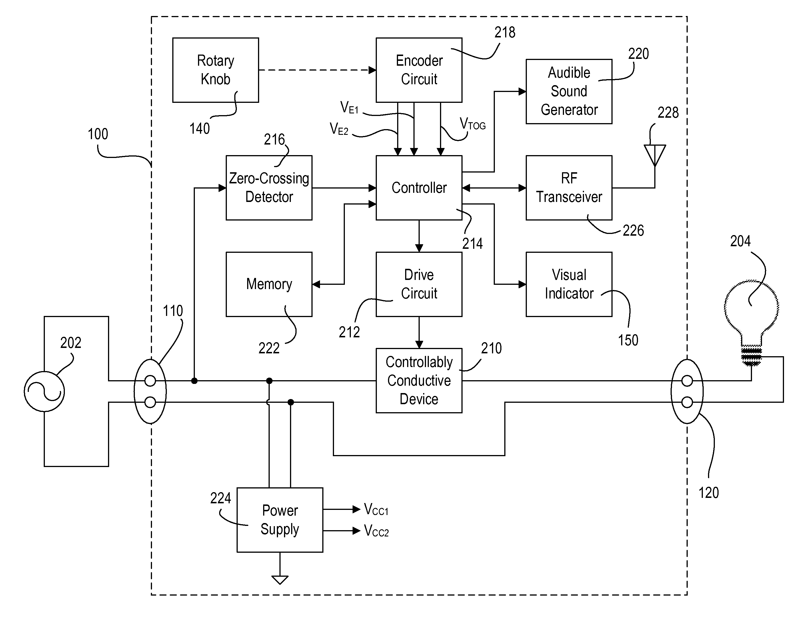
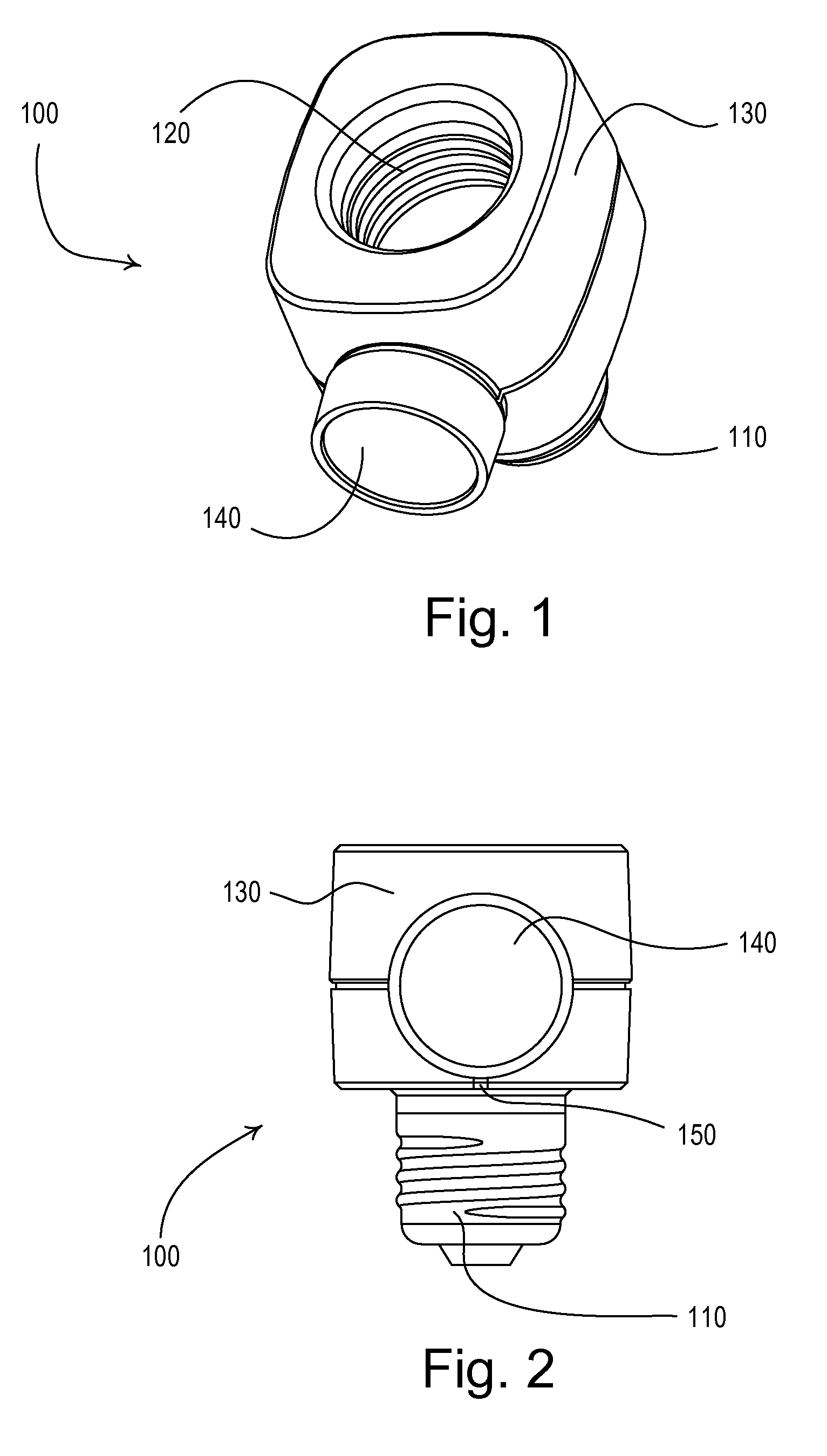
[0031]FIG. 1 is a perspective view and FIG. 2 is a front view of a “smart” electronic lamp control module 100 according to the present invention. The lamp control module 100 has a screw-in base 110, such that the lamp control module 100 is adapted to be screwed into a standard Edison socket. The lamp control module 100 also includes a socket portion 120 (e.g., a standard Edison socket), such that a lighting load 204 (FIG. 4), for example, a standard incandescent lamp, may be cou...


PUM


Abstract

A load control device for controlling the amount of power delivered from an AC power source to an electrical load comprises a rotary actuator, such as a rotary knob or a rotary wheel. The load control device increases and decreases the amount of power delivered to the electrical load in response to rotations of the rotary knob in first and second directions, respectively. The load control device accelerates the rate of change of the amount of power delivered to the load in response to the angular velocity of the rotary actuator. The load control device generates a ratcheting sound when the rotary actuator is rotated in the first direction at a high-end intensity of the load control device. The load control device is operable to control the electrical load in response to both actuations of the rotary actuator and digital messages received via a communication link.

Description

BACKGROUND OF THE INVENTION[0001]1. Field of the Invention[0002]The present invention relates to a load control device for controlling the amount of power delivered from an alternating-current (AC) power source to an electrical load, and more particularly, to a smart lighting control device having a rotary intensity adjustment actuator, such as a rotary knob or a rotary wheel, for control of the intensity of a connected lighting load.[0003]2. Description of the Related Art[0004]A conventional wall-mounted load control device is mounted to a standard electrical wallbox and is coupled between an alternating-current (AC) power source (typically 50 or 60 Hz line voltage AC mains) and an electrical load. Standard load control devices, such as dimmers and motor speed controls, use a bidirectional semiconductor switch, such as a triac, or one or more field effect transistors (FETs), to control the current delivered to the load, and thus, the intensity of the lighting load or the speed of t...

Claims


Application Information

Patent Timeline
Patent Type & Authority Patents(United States)
IPC IPC(8): H05B37/02
CPCH05B39/041H05B39/08H05B37/02H05B39/085H05B41/3921H05B39/083H05B47/10H05B47/165Y02B20/40
Inventor BIERY, ETHAN CHARLESKNODE, GALEN EDGARLOPEZ, CLIVE ELTONSPIRA, JOEL S.FLOWERS, MAUREEN E.
Owner LUTRON TECH CO LLC
Why Eureka
Try Eureka