
Sealing patch for the ventilation hole of a non-siliconized cushion of an airbag module

a non-siliconized cushion and ventilation hole technology, applied in the field of sealing patches for ventilation holes of non-siliconized cushion, can solve the problems of patch failure, increased cushion cost, and possibility of causing injuries when actuated

Active Publication Date: 2011-01-25
DALPHI METAL ESPANA
View PDF19 Cites 4 Cited by
  • Summary
  • Abstract
  • Description
  • Claims
  • Application Information

AI Technical Summary

Benefits of technology

The present invention provides an airbag module with a cushion made without any silicone coating and having at least one ventilation hole sealed by a silicone membrane or similar elastic material. The invention also provides a process for manufacturing the cushion with the sealing patch. The technical effects of this invention include improved airbag safety and protection for drivers and passengers in the event of a collision, as well as simplified manufacturing processes.

Problems solved by technology

To prevent the cushion from being too stiff when it comes into contact with the driver or passenger, acting as if it were a ball and making the rebound effect cause an excessive impact in the person for whom it deploys, they have been provided with a ventilation hole used to reduce the internal pressure of the cushion and, consequently, the possibility of causing injuries when actuated.
Fabric patches such as those described in patent documents U.S. Pat. No. 3,879,057, U.S. Pat. No. 4,097,065 and U.S. Pat. No. 5,018,761 have been proposed, said patches not being successful due to the lack of breaking pressure uniformity as a result of their nature.
Nor have plastic patches such as those proposed in patent document U.S. Pat. No. 3,573,885 been successful because of the difficulty in controlling their breaking pressure due to the variability of mechanical characteristics of plastic at different temperatures.
The cushions to which said patches are fixed must be coated with silicone to facilitate fixing the patch to the cushion by means of a gluing process, which involves a drawback because this coating increases the cost of the cushion and reduces its packaging capacity.

Method used


Image

  • Sealing patch for the ventilation hole of a non-siliconized cushion of an airbag module
  • Sealing patch for the ventilation hole of a non-siliconized cushion of an airbag module

Examples


Embodiment Construction

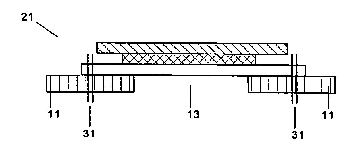
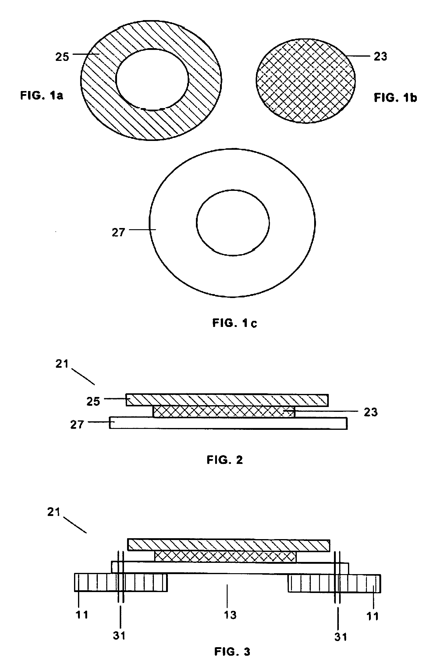
[0021]In a preferred embodiment of the invention the patch 21 is formed by joining a silicone membrane 23, an upper piece 25 of calendered fabric and a lower piece 27 of fabric coated with silicone on the face adjacent to the membrane 23.

[0022]The membrane 23 has a circular shape and pieces 25 and 27 have an annulus shape with an outer diameter larger than that of the membrane 23 and with an inner diameter smaller than that of the membrane 23.

[0023]The patch 21 is joined to the cushion 11 by means of seams 31 traversing its lower piece 27 but not the membrane 23. In another embodiment, the seams 31 would also include the upper piece 25.

[0024]A suitable process for manufacturing the patches 21 is the following: the membrane 23 is arranged on the piece 25 of calendered fabric (along its siliconized face) and the piece 27 of coated fabric is arranged on the membrane (along its siliconized face). The assembly is subjected to a vulcanizing press during the time and at the temperature nec...


PUM


Abstract

The invention relates to an airbag module for protecting an occupant of a vehicle in the event of a collision, comprising a cushion (11) that can expand with the gas provided by a generator with at least one ventilation hole (13) sealed with a patch (21) including a silicone membrane (23) intended to break due to the effect of the internal pressure in the cushion (11) so as to allow gas discharge, in which the fabric of the cushion (11) does not have a silicone coating, the patch (21) is formed by said membrane (23) joined at its edges to two pieces (25, 27) of fabric and fixed to the cushion (11) by means of a seam (31). The invention also comprises a process for manufacturing the cushion (11).

Description

FIELD OF THE INVENTION[0001]The present invention relates to an airbag module intended for protecting an occupant of a vehicle in the event of a collision and particularly a sealing patch for the ventilation hole of a non-siliconized cushion.[0002]The present invention can be applied to the automobile industry in general, and particularly to the field dedicated to manufacturing and / or installing and / or assembling auxiliary equipment and active safety devices in vehicles.BACKGROUND OF THE INVENTION[0003]Airbag modules consist of casings in which a folded cushion is fixed, which cushion quickly inflates by means of a gas produced by a generator when specific sensing devices detect a vehicle collision. The cushion thus deploys in front of the driver or a passenger, depending on its location, and prevents their bodies from hitting against any part of the vehicle.[0004]To prevent the cushion from being too stiff when it comes into contact with the driver or passenger, acting as if it wer...

Claims


Application Information

Patent Timeline
Patent Type & Authority Patents(United States)
IPC IPC(8): B60R21/276
CPCB60R21/239
Inventor CARVALHO MARQUES, ALEXANDRE JOSE
Owner DALPHI METAL ESPANA
Learn More