Ink jet printer

a jet printer and printer body technology, applied in the field of jet printers, can solve the problems of unstable quantity of jetted ink, end of image, and increase in jetted ink quantity, and achieve the effect of reducing the number of droplets

Active Publication Date: 2011-01-25
RISO KAGAKU CORP
View PDF8 Cites 0 Cited by
  • Summary
  • Abstract
  • Description
  • Claims
  • Application Information

AI Technical Summary

Benefits of technology

[0014]The invention is made to solve the problems of the above-mentioned conventional type ink jet head and the object is to settle a phenomenon that the quantity of jetted ink increases at the end of an image and the density increases in a shear-mode ink jet head so as to reduce density nonuniformity. In the shear-mode ink jet head, a phenomenon that the jetted quantity increases at a joint of the head and the density increases occurs, however, the further object of the invention is to settle the phenomenon so as to reduce density nonuniformity.
[0016]An ink jet printer disclosed in a second aspect is based upon an ink jet printer in which plural nozzles of an ink jet head in a shear-mode are split into plural groups and printing is simultaneously performed per group, and is characterized in that further when the same drop amount is jetted from plural nozzles that belong to another group on a side of jet nozzles while one nozzle adjacent to a target nozzle is a non-jet nozzle and a drop amount jetted from the other nozzle adjacent to the target nozzle is the same as a drop amount of the target nozzle, density correction control of reducing the drop amount of the target nozzle is made.
[0021]An ink jet printer disclosed in a seventh aspect is based upon the ink jet printer disclosed in the sixth aspect, and is characterized in that an ink jet quantity is variable by varying the number of droplets and density correction control is made by reducing the number of droplets.
[0023]An ink jet printer disclosed in a ninth aspect is based upon an ink jet printer which is provided with plural shear-mode ink jet heads, in which plural nozzles of each of the ink jet heads are split into plural groups and in which printing is simultaneously performed per group, and is characterized in that when a drop amount jetted from a nozzle at the end of nozzles that simultaneously jet ink of a first ink jet head and a drop amount of each of plural nozzles of an adjacent second ink jet head that jet ink toward a dot position adjacent to a drop jetted from the nozzle at the end of the first ink jet head and toward a dot position in an internal direction of the second ink jet head are the same, density correction control of reducing a quantity of ink jetted from the nozzle at the end of the first ink jet head is made.
[0028]An ink jet head disclosed in a fourteenth aspect is based upon the ink jet head disclosed in the thirteenth aspect, and is characterized in that a drop amount can be varied by varying the number of multiple droplets and the number of droplets is reduced in density correction control.

Problems solved by technology

According to the shear-mode ink jet head, nozzles at both ends out of multiple nozzles arranged in a main scanning direction have a tendency that the quantity of jetted ink is unstable because the nozzles at both ends are different in a condition from inside nozzles surrounded by each nozzle at both ends, the quantity of jetted ink increases at the end of an image and the density increases.
As a result, it is difficult to completely solve a phenomenon that the quantity of jetted ink increases at the end of an image and the density increases by the above-mentioned shear-mode ink jet head.
In addition, there is another problem that when plural shear-mode ink jet heads described above are used with them arranged, the quantity of jetted ink increases in a boundary between head modules, printing density increases and striped density nonuniformity emerges in a part equivalent to the boundary.
Further, in configuration like a line printer, plural heads are arranged in line, however, as adjacent heads are arranged off in a sub-scanning direction so that nozzles for a few dots are overlapped in the sub-scanning direction, the configuration has a problem that the number of dots overlapped at the ends of the heads further increases and density nonuniformity in a boundary between head modules becomes more conspicuous.

Method used


Image

  • Ink jet printer
  • Ink jet printer
  • Ink jet printer

Examples


first embodiment

1. First Embodiment

The Invention Related to First to Seventh Aspects

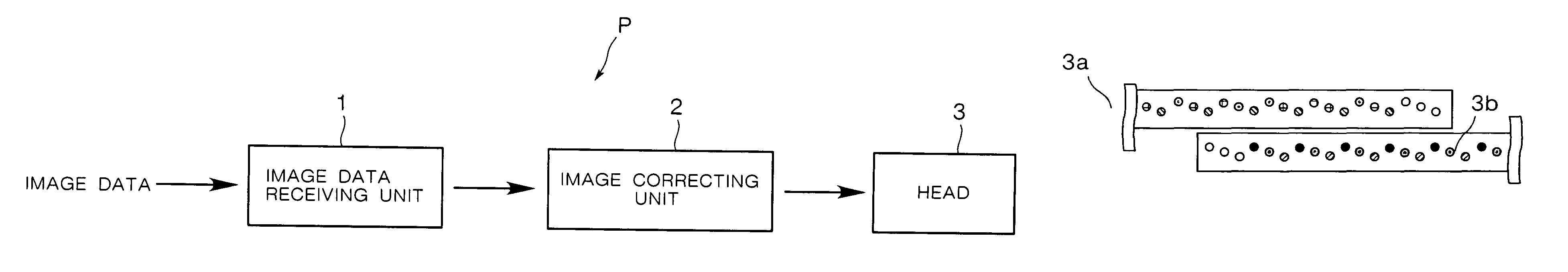
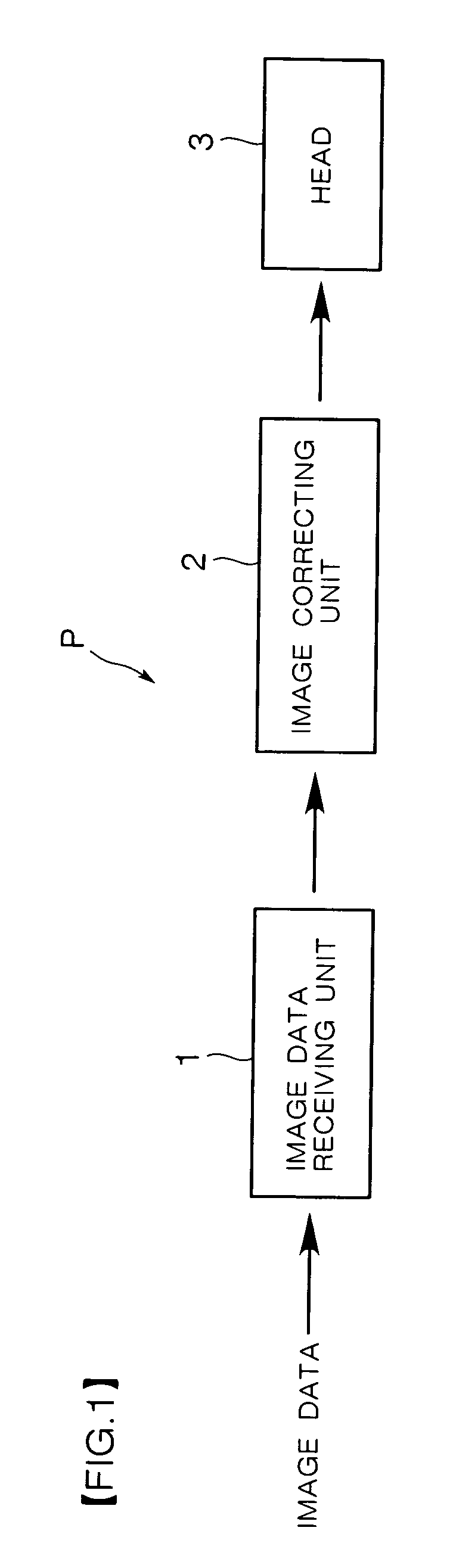
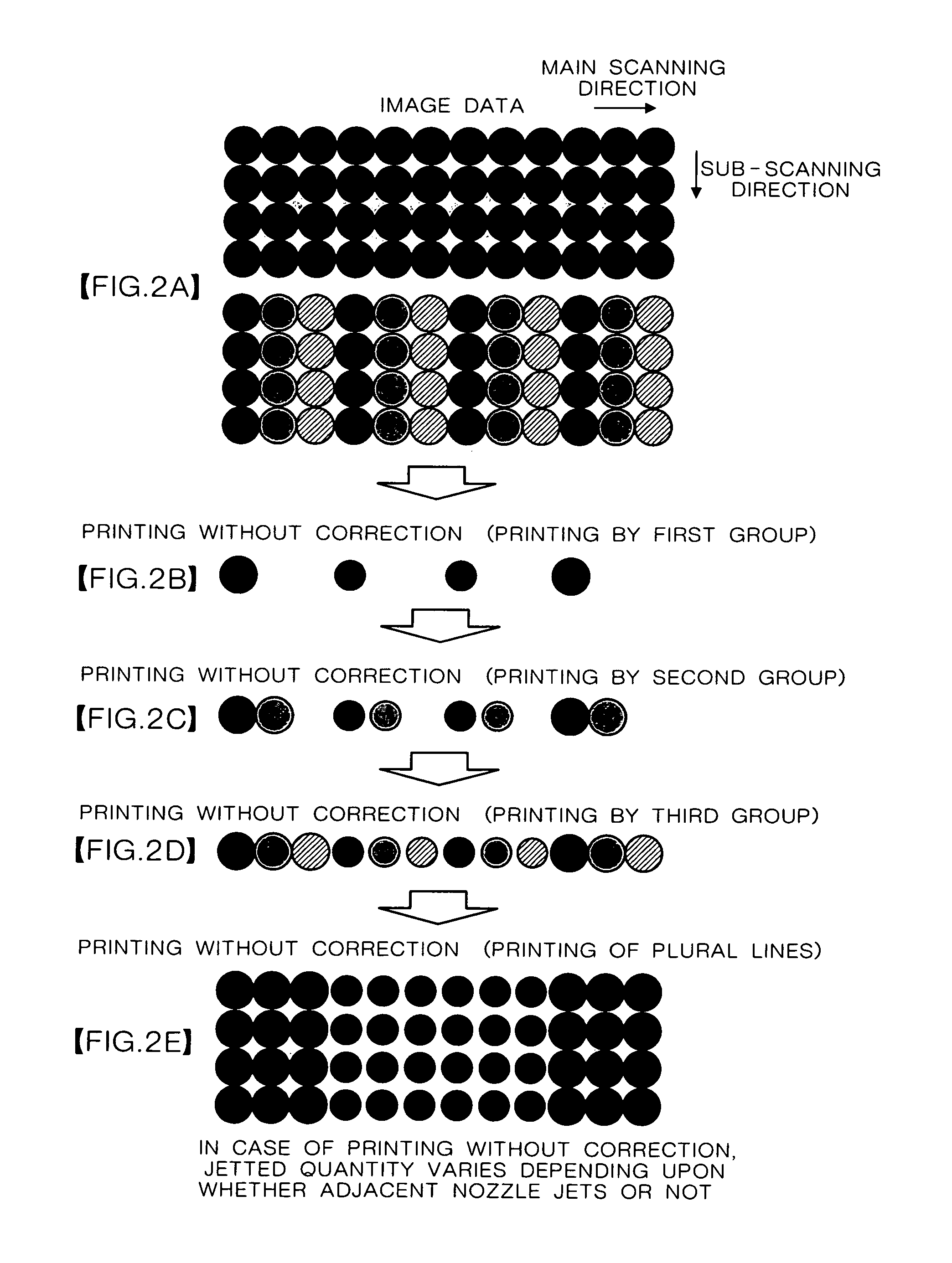
[0038]Referring to FIGS. 1 to 5, a first embodiment will be described below. FIG. 1 is a block diagram showing the configuration of an ink jet printer P equivalent to this embodiment, FIGS. 2A to 2E are dots enlarged views showing a problem caused in the case of printing without correction, FIGS. 3A to 3E are dots enlarged views showing a case of printing with correction, and FIGS. 4A to 4E are dots enlarged views showing a case of printing with correction by another correction method.

(1) Configuration

[0039]As shown in FIG. 1, this ink jet printer P is provided with an image data receiving unit 1 that receives image data and converts it to data suitable for the formation of an image by an ink jet head, an image correcting unit 2 that corrects the data from the image data receiving unit 1 so as to enable suitably controlling a drop amount of jetted ink and an ink jet head 3 (head 3) that forms an image on paper and o...

second embodiment

2. Second Embodiment

The Invention Related to Eighth to Fourteenth Aspects

[0060]Referring to FIGS. 5A to 5J and 6A to 6J, a second embodiment will be described below. FIGS. 5 A to 5J are dots enlarged views showing a problem caused in the case of printing without correction and FIGS. 6A to 6J are dots enlarged views showing a case that the quantity of jetted ink is corrected by a correcting method according to the invention.

(1) Configuration

[0061]The whole configuration in this embodiment is substantially similar to that of the first embodiment shown in FIG. 1. However, plural heads 3 each of which is split into three as in the first embodiment are used, as shown in FIG. 5B and FIG. 6B, these are arranged in a main scanning direction, joints are set off in a sub-scanning direction, and each corresponding dot in the similar positions in the main scanning direction of adjacent heads 3a, 3b is located off by a predetermined dimension in the sub-scanning direction.

[0062]This embodiment r...


PUM


Abstract

In order to settle a phenomenon that a quantity of jetted ink increases at the end of an image and a density increases in a shear-mode ink jet head, in a three-split driven head, a first group prints so that a diameter of a dot is reduced by reducing the quantity of jetted ink as dots at both ends, a second group similarly prints, and a third group also similarly prints. Since three dots at both ends in a main scanning direction of an acquired image are smaller than dots in the middle, the phenomenon that a quantity of jetted ink increases at the end of the image and density increases is reduced.

Description

FIELD OF THE INVENTION[0001]The present invention relates to an ink jet printer using a shear-mode ink jet head that corrects density nonuniformity which is apt to be caused at the end of an image and at a joint of a head and can enhance the quality of an image.BACKGROUND OF THE INVENTION[0002]An ink jet printer that uses a shear-mode ink jet head is known. The shear-mode inkjet head has a two-layer structure in which two piezoelectric members polarized in a mutually opposite direction in a direction of the thickness are pasted via an adhesive, the two piezoelectric members are cut so that multiple grooves pass pasted faces at a fixed interval, a comb structure that the end of each groove is open at the front end of a plate is formed, and the upside of these grooves is closed by another plate. The rear end of each groove communicates with a common ink chamber and an orifice plate having an ink jet (a nozzle) in a position of each groove is provided to an opening at the end. An elect...

Claims


Application Information

Patent Timeline
Patent Type & Authority Patents(United States)
IPC IPC(8): B41J29/38
CPCB41J2/04508B41J2/04543B41J2/04581B41J2202/10B41J2202/20B41J29/38
Inventor BANSYO, TOSHIHIRO
Owner RISO KAGAKU CORP
Why Eureka
Try Eureka