Marker or filler forming fluid

a filler and marker technology, applied in the field of filler or marker material introduction into the patient's body, can solve the problems of radiographically visible tissue features, altered or obscured, days or weeks before,

Active Publication Date: 2011-01-25
SENORX
View PDF123 Cites 54 Cited by
  • Summary
  • Abstract
  • Description
  • Claims
  • Application Information

AI Technical Summary

Benefits of technology

[0016]The detectable marker mass which forms in the biopsy cavity should be large enough to fill a substantial portion, preferably all of the cavity. This allows the detection and definition of the boundaries of the biopsy cavity. The accessing passageway leading to the biopsy cavity may also at least in part be filled with the marker fluid as well if desired, which allows the physician to follow to locate the marker mass. The marker mass which forms in the cavity is ultrasonically detectable, but the marker fluid may also include ultrasonically or radiographically detectable powders or other particulate to augment the detection of the polymeric mass or the biopsy cavity. Other therapeutic and diagnostic agents may be incorporated into the marker fluid such as pharmaceutical agents, chemotherapeutic agents, anesthetic agents, hemostatic agents, pigments, dyes, radiopaque agents, materials detectable by magnetic resonance imaging (MRI), inert materials, and other compounds.
[0018]The biopsy site markers formed by the present invention provide ultrasonically bright images which can be readily distinguished from the ultrasound signals arising naturally from within a breast or other tissue and which readily contrasts with the dark ultrasound shadow region immediately behind the bright ultrasound echo region. The strength of the reflected signal, and the contrast with the shadow region, make the marked site readily detectable even to relatively inexperienced surgeons. The in-vivo lifetime of the marker at the biopsy site can be preselected by adjusting the amount of polymeric material in the marker fluid and the molecular weight thereof. The employment of the filler forming functions of the solution may be advantageously utilized in cosmetic treatments similar to the uses of collagen, e.g. wrinkle removal or minimization, or in situations in which additional bulk is needed within a patient's body, e.g., treating for urinary incontinence.

Problems solved by technology

After the biopsy sample is taken, it may take several days or weeks before the results of the examination of the sample are obtained, and still longer before an appropriate treatment decision is reached.
However, radiographically visible tissue features, originally observed in a mammogram, may be removed, altered or obscured by the biopsy procedure.
However, due to the consistency of breast tissue and the fact that these biopsy site markers are typically introduced while the breast is still compressed between the mammography plates, prior art biopsy markers may not remain at the specific biopsy location after the breast has been decompressed and removed from the mammography apparatus, and may suffer from additional disadvantages as well.
However, as the patient is removed from the mammography apparatus, or otherwise transported, the position of the location wire can change or shift before the treatment or surgery is performed, which may result in treatments being misdirected to undesired locations.
Furthermore, at least some prior art biopsy site markers can remain present at the site of implantation for an indefinite period of time and, if not surgically removed, may obscure or otherwise interfere with any subsequent mammography or imaging studies.
However, due to the large amount of fibrous tissue normally present in a human breast, and due to the presence of ligaments running through the breast, a marker that simply has a bright signal alone will not provide a useful signal that is readily discernable from the many anatomic features normally present within a human breast.
Such markers are typically small, being sized to fit within a syringe or other delivery tube, and so are often not readily distinguishable from natural features of the breast, which include occasional small ultrasound-bright spots.
However, radiopaque markers may not be visible with USI.
A marker visible with USI enables a follow-up procedure to be performed without the need for traditional radiographic mammography imaging which, as discussed above, can be subject to inaccuracies as a result of shifting of the location wire as well as being tedious and uncomfortable for the patient.

Method used


Image

  • Marker or filler forming fluid
  • Marker or filler forming fluid
  • Marker or filler forming fluid

Examples


Embodiment Construction

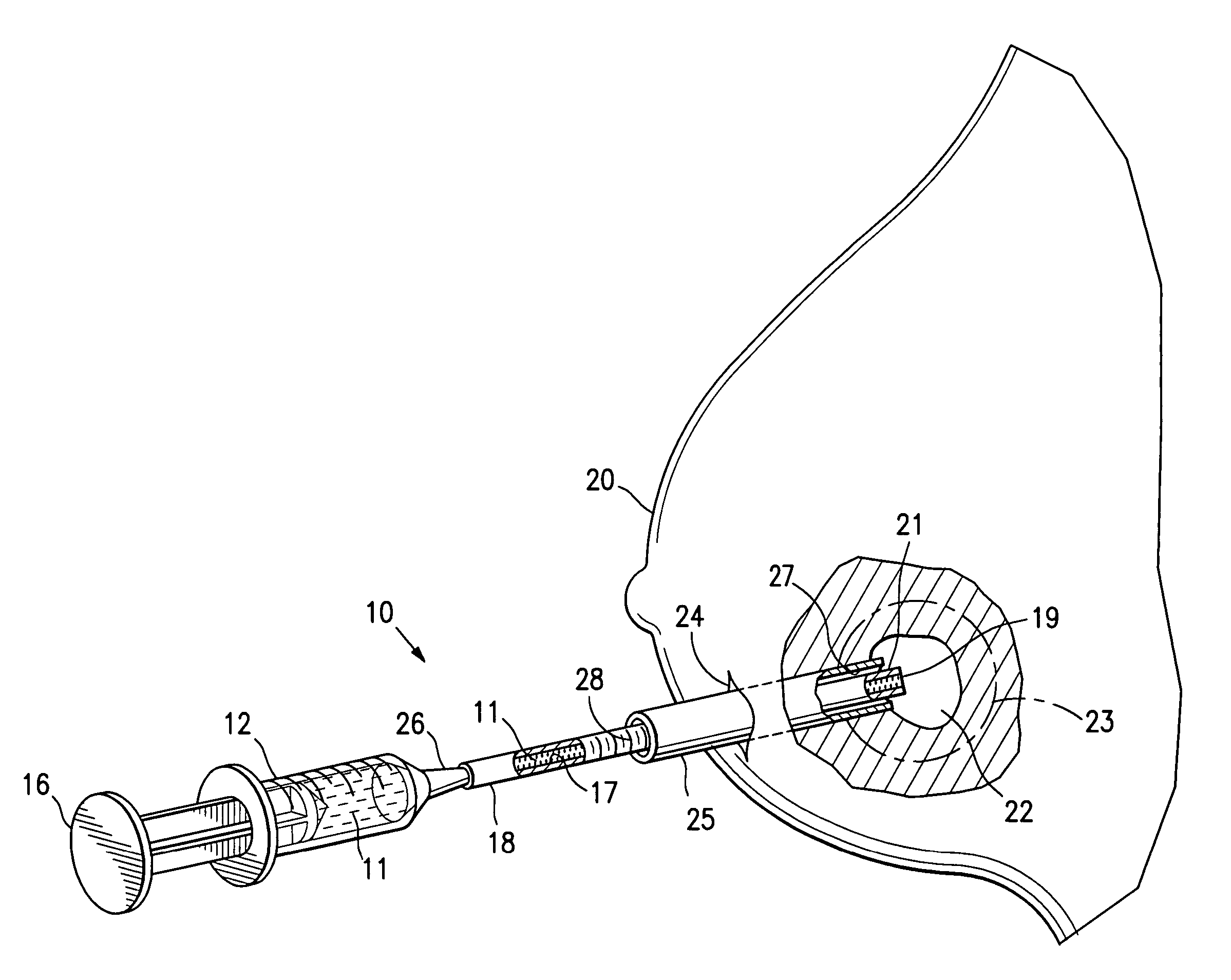
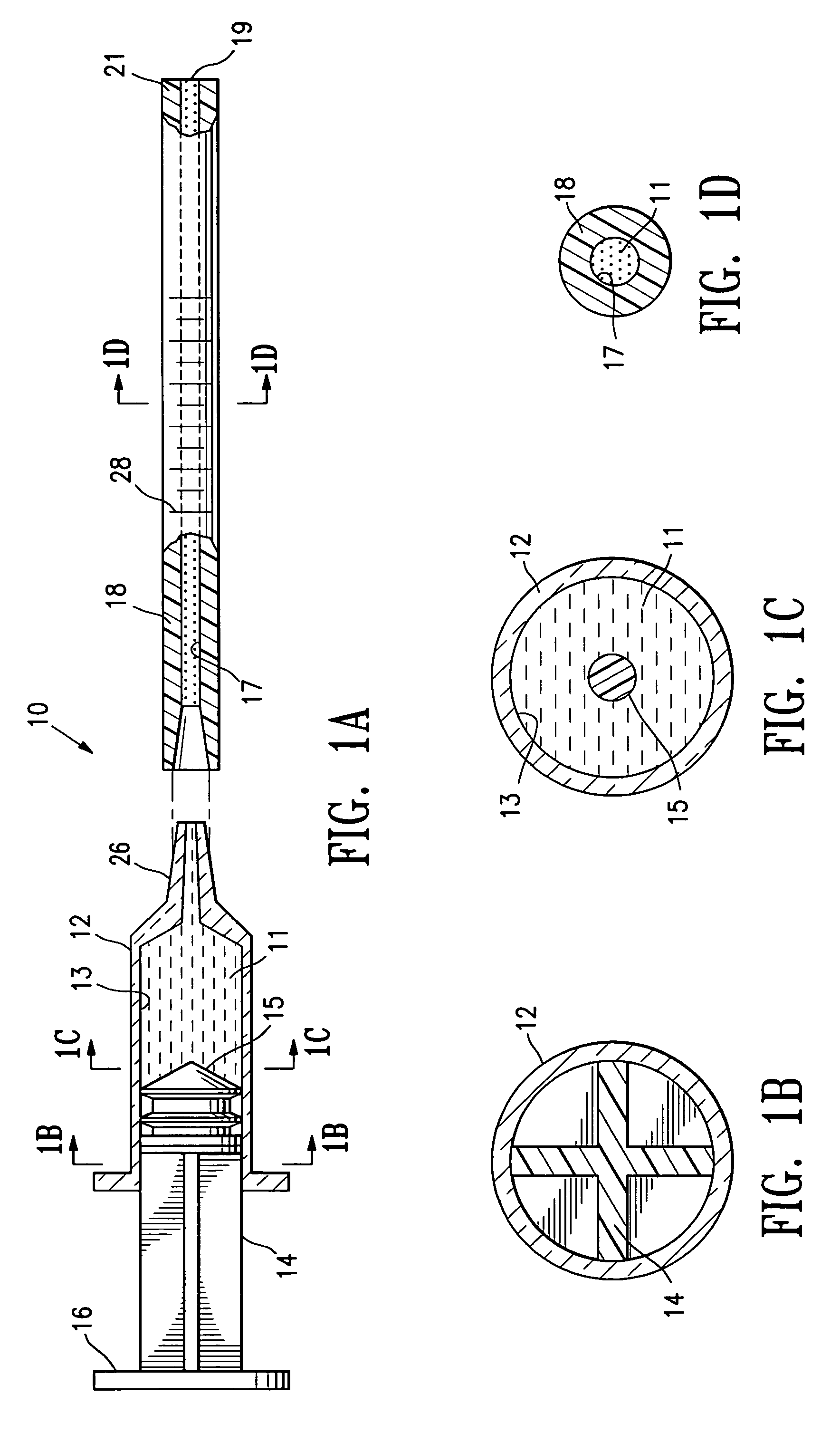
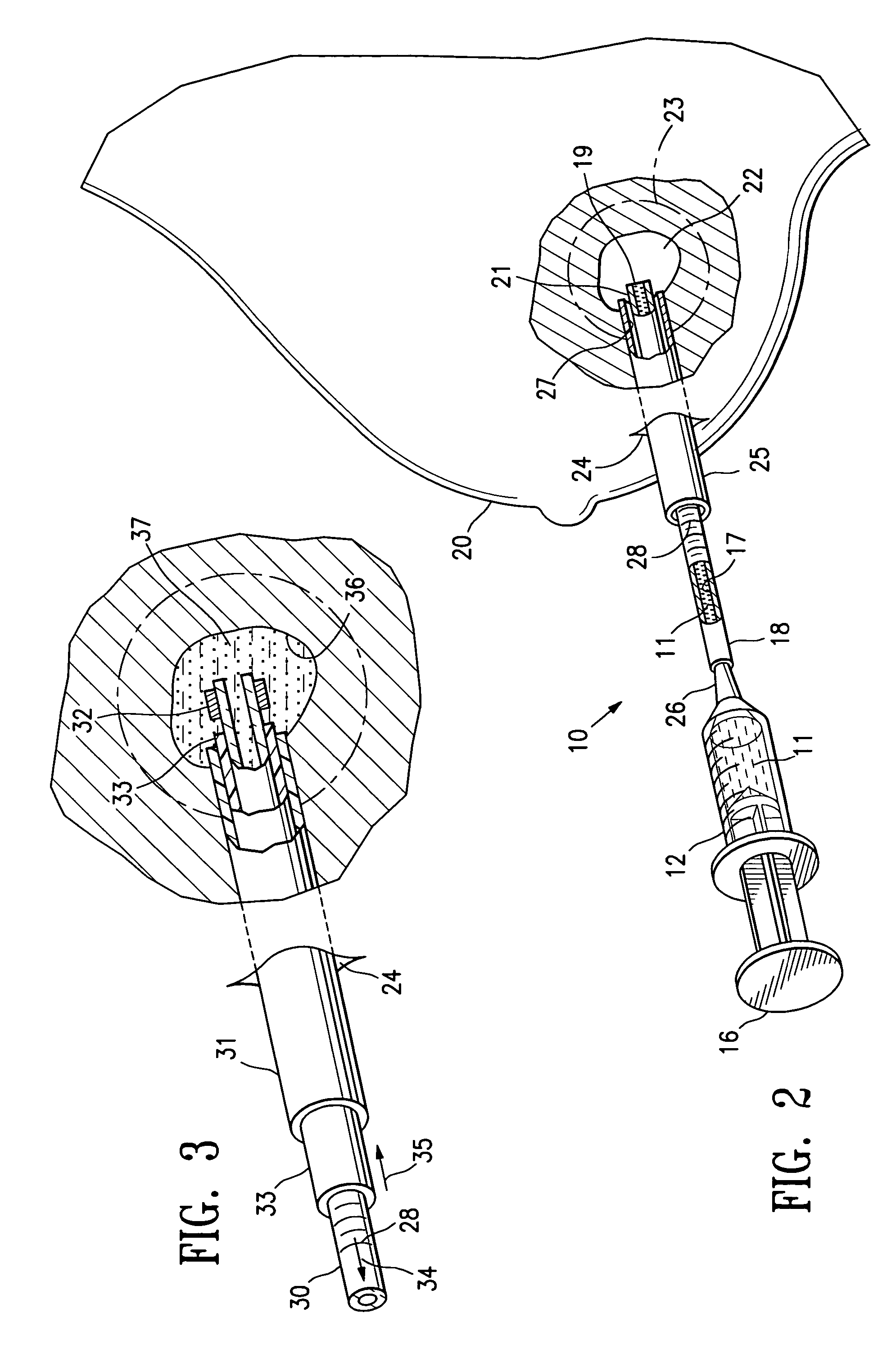
[0030]FIGS. 1A-1D illustrate a system 10 for delivery of biopsy marker fluid 11 embodying features of the invention to a biopsy site within a patient's body. The system 10 includes a syringe 12 having a bore 13 containing a quantity of biopsy marker fluid 11. A plunger 14 with a sealable distal end 15 is slidably disposed within the bore 13 of syringe 12. Application of pressure to the head 16 of plunger 14 applies pressure to the fluid 11 and causes the discharge of fluid 11 from the bore 13 into the inner lumen 17 of delivery tube 18 secured to the discharge end of syringe 12. The marker fluid 11 passes through the inner lumen or bore 17 of the delivery tube 18 and out the discharge port 19 in the distal end of delivery tube 18.

[0031]As schematically illustrated in FIG. 1A, delivery tube 18 is secured to the syringe 12 by a friction fit. However, those skilled in the art will recognize that a variety of connections may be made between the syringe 12 and the delivery tube 18 such a...


PUM


Abstract

A solution for forming a marker or filler mass for an intracorporeal site. The solution contains a polar, water soluble non-aqueous solvent such as dimethyl sulfoxide and a bioabsorbable, essentially water insoluble polymer such as polylactic acid, or copolymers of lactic acid and glycolic acid. The solution may be delivered to the biopsy site by a suitable syringe and delivery tube. The delivery tube is preferably provided with a releasable radiopaque element on the distal tip which can be released within the polymeric marker mass formed in the biopsy cavity.

Description

FIELD OF THE INVENTION[0001]This invention relates generally to the introduction of filler or marker material into a patient's body, and particularly to the filling of a biopsy site within a patient's body from which a biopsy specimen has been taken with a mass of marker material.BACKGROUND OF THE INVENTION[0002]In diagnosing and treating certain medical conditions, it is often desirable to perform a biopsy, in which a specimen or sample of tissue is removed for pathological examination, tests and analysis. As is known, obtaining a tissue sample by biopsy and the subsequent examination are typically employed in the diagnosis of cancers and other malignant tumors, or to confirm that a suspected lesion or tumor is not malignant. The information obtained from these diagnostic tests and / or examinations is frequently used to devise a plan for the appropriate surgical procedure or other course of treatment. For example, breast biopsies may be taken where a suspicious lump or swelling is n...

Claims


Application Information

Patent Timeline
Patent Type & Authority Patents(United States)
IPC IPC(8): A61B6/00A61B10/00A61B19/00A61K49/22
CPCA61B19/54A61K49/226A61B2019/5408A61B2019/5433A61B2019/5487A61B2019/5425A61B90/39A61B2090/3908A61B2090/3925A61B2090/3933A61B2090/3987
Inventor BURBANK, FRED H.JONES, MICHAEL L.LOUW, FRANKLUBOCK, PAUL
Owner SENORX
Why Eureka
Try Eureka