
One-piece float switch housing and drain line assembly with condensate collection pan

a float switch and condensate collection technology, applied in the direction of defrosting, heating types, domestic cooling apparatus, etc., can solve the problems of back-up and/or overflow of the system producing the remaining, and achieve the effect of convenient and prompt installation, convenient and quick attachment, and proper and reliable operation

Active Publication Date: 2011-02-01
RECTORSEAL LLC
View PDF3 Cites 20 Cited by
  • Summary
  • Abstract
  • Description
  • Claims
  • Application Information

AI Technical Summary

Benefits of technology

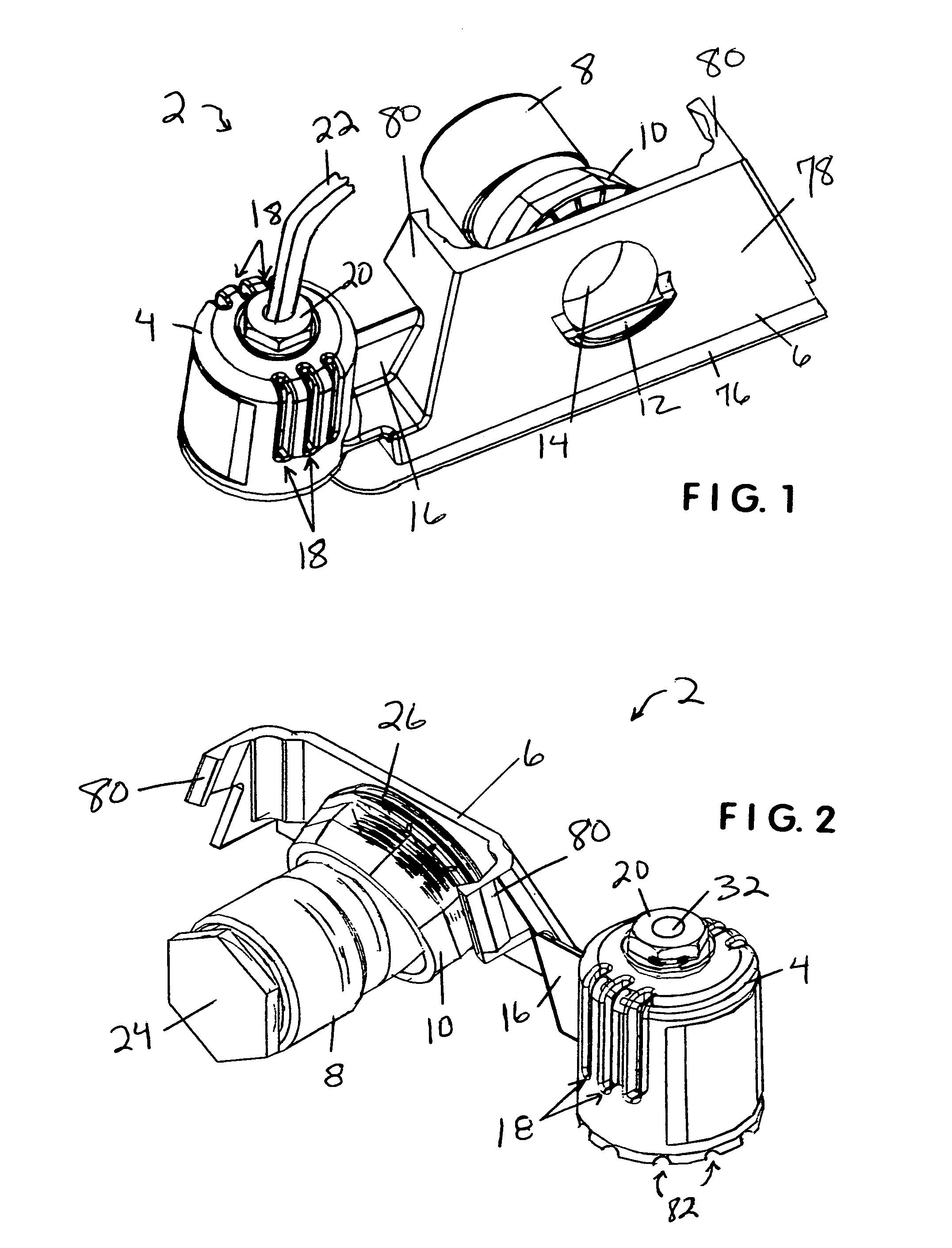
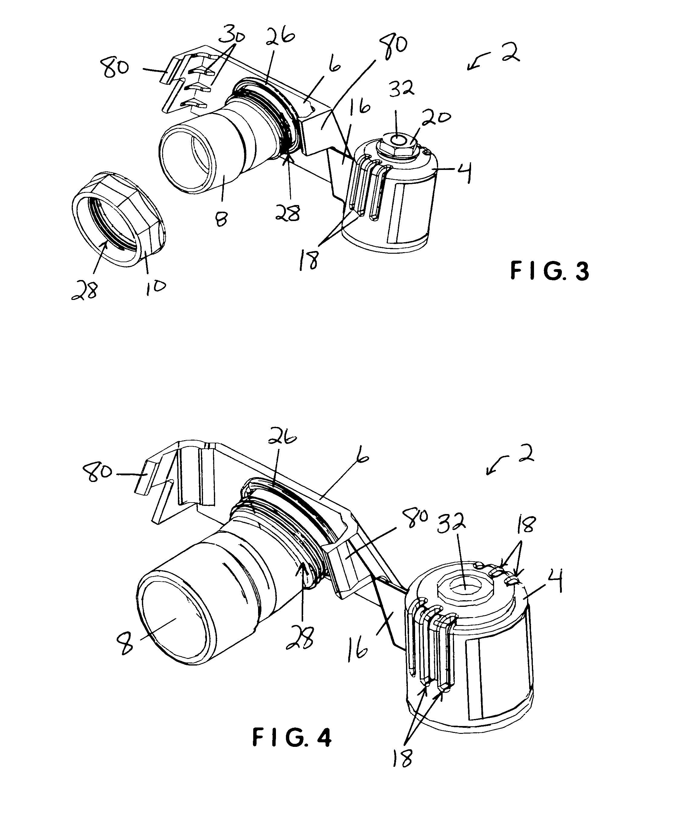
"The present invention is a one-piece liquid-level float switch and drain line assembly that can be easily attached to a condensate collecting tray / pan and is designed to provide reliable and reproducible operation. The assembly is made from corrosion-resistant materials that resist premature deterioration and malfunction in the face of temperature variations. It is also designed to promote proper and reliable operation by facilitating condensate collection within its float housing, providing adequate air venting, and protecting its float switch body from damage. The assembly can be quickly installed and is easy to maintain. It is also designed to shut off the source of condensate production when the level of condensate in the tray / pan exceeds a pre-established threshold level, preventing damage to the system and ensuring reliable and long-term operation."

Problems solved by technology

When air conditioning condensate and other condensates are collected in a pan or tray to avoid immediate condensate contact with surrounding objects and structure, risks of overflow and / or back-up into the system producing it remain.

Method used


Image

  • One-piece float switch housing and drain line assembly with condensate collection pan
  • One-piece float switch housing and drain line assembly with condensate collection pan
  • One-piece float switch housing and drain line assembly with condensate collection pan

Examples


first embodiment

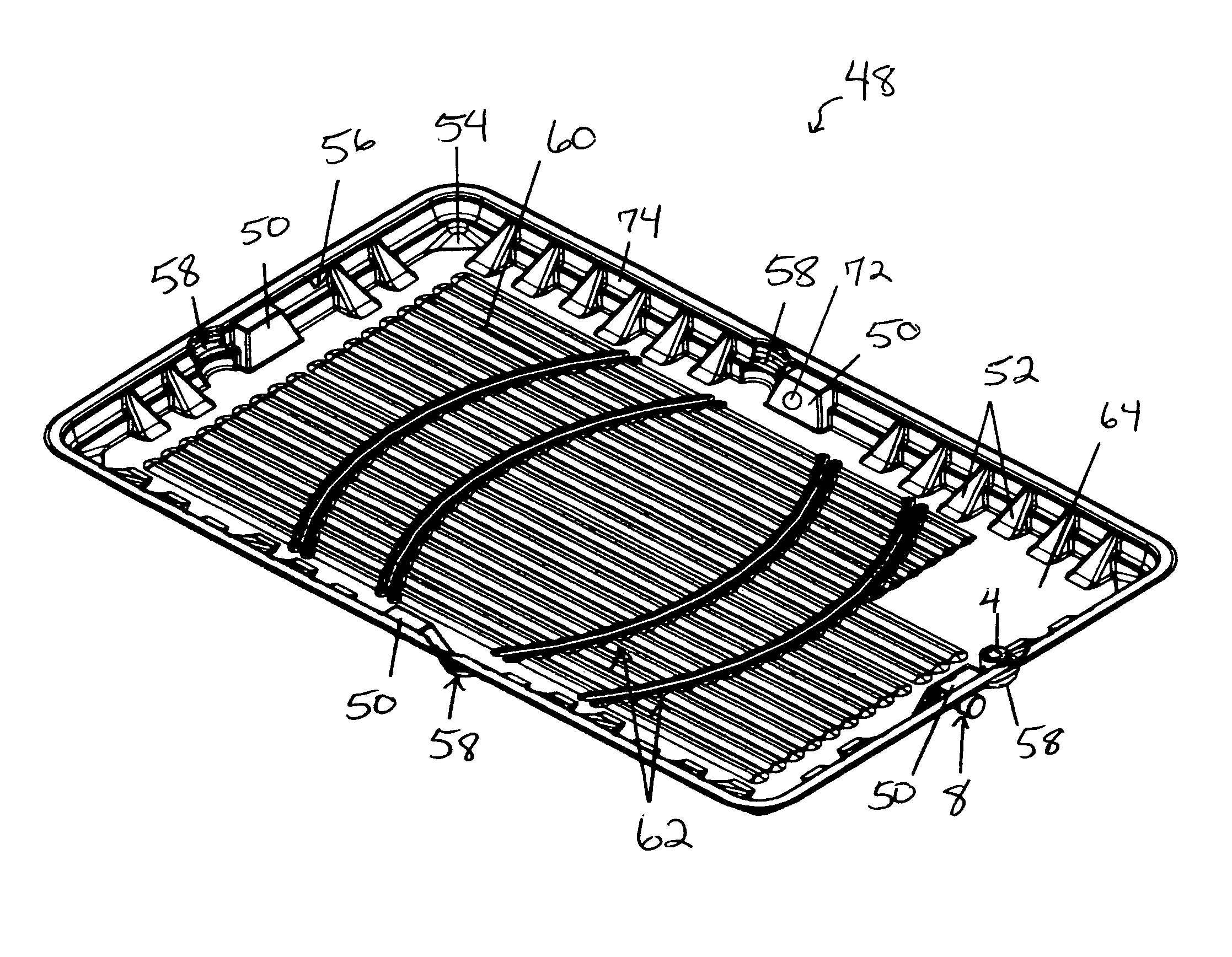
[0027]FIGS. 8 and 9 show a first preferred embodiment of a condensate collection pan / tray 48 contemplated for use with the present invention assembly 2. FIG. 8 shows condensate collection pan / tray 48 having a raised central portion, a perimeter wall 74, a plurality of gussets 52 between the central portion and perimeter wall 74, an assembly-mounting support shelf 50 on each wall, a horizontally-extending concave ribbed configuration 58 adjacent to each support shelf 50, an assembly 2 mounted on the support shelf 50 in the right-hand portion of the illustration, angled corner supports 54, and a horizontally-extending ridge 56 on perimeter wall 74 between adjacent gussets 52 and above the angled corner supports 54. All are configured for strengthening pan / tray 48 from premature cracking and / or deterioration during installation and use. FIG. 8 shows the raised pattern in the central portion of pan / tray 48 having a two-part configuration consisting of multiple longitudinally-extending l...

embodiment 2

[0029]It is contemplated for the present invention pans / trays 48, 66, and other embodiments to replace metal pans (not shown) that rust out when the air conditioning air handlers they support sweat and produce condensation, and for assembly 2 to be used with the present invention pans / trays 48, 66, and other embodiments. However, in the reverse it is contemplated assembly 2 to also be used with prior art trays / pans, even though use of the present invention pan / trays 48, 66, and other embodiments will significantly reduce installation times. When the present invention assembly 2 and a pan / tray 48, 66, or other with a support shelf 50 are used together, assembly 2 can be rapidly secured during manufacture or by an installer through a pre-formed drain line opening 72 in the pan's / tray's perimeter wall 74. Such connection can be easily made using a threaded connector 10 and an O-ring 26 or other seal (not shown) that in combination provide a leak-resistant connection. For most expeditio...


PUM


Abstract

A one-piece liquid-level float switch housing and drain line assembly for use with a collection tray or pan to collect condensate and shut off the source of condensate production when it exceeds a pre-established threshold level. The assembly is configured for rapid connection through a pre-formed drain line opening in the perimeter wall of a condensate collection tray / pan to place the deployable float body within its housing in a level orientation relative to the tray / pan without additional leveling adjustment. The housing has an open bottom and vertically-extending slots providing fluid inlet, debris blocking, and air venting functions for enhanced float body operation. The condensate pan / tray used with the assembly has a nesting configuration that includes a perimeter wall with varying combinations of gussets, curved ribs, angled corner configurations, and support shelves, and a central bottom surface with raised patterns, all of which strengthen the tray / pad during installation and use.

Description

CROSS-REFERENCES TO RELATED APPLICATIONS[0001]None.BACKGROUND[0002]1. Field of the Invention[0003]This invention relates to condensate pans and liquid-level float switches, specifically to a one-piece liquid-level float switch housing and drain line assembly for use in combination with a collection tray or pan to collect condensate and shut off the source of condensate production when it exceeds a pre-established threshold level. The present invention tray / pan is preferably made from plastic materials such as ABS or polycarbonate, although not limited thereto, and has a sturdy perimeter wall surrounding a raised central portion, which supports the condensate producing system above the maximum level of condensate anticipated for collection in the tray / pan prior to system shut off. The combination of gussets, ribs, shelves, and other reinforcing structures used in the present invention tray / pan are configured to strengthen the tray / pan against cracking and other potentially deteriorat...

Claims


Application Information

Patent Timeline
Patent Type & Authority Patents(United States)
IPC IPC(8): F25D21/14
CPCF24F13/222F24F2011/0054F25D21/14F24F2140/30
Inventor CANTOLINO, CHRISTOPHER RALPH
Owner RECTORSEAL LLC
Learn More