Method and apparatus for enhancing engine-powered lift in an aircraft

a technology of engine-powered lift and aircraft, which is applied in the direction of airflow influencers, jet flaps, vertical landing/take-off aircraft, etc., can solve the problem of increasing the amount of lift produced along the surface of the airfoil, and achieve the effect of increasing the lift produced along the surfa

Inactive Publication Date: 2011-02-01
THE BOEING CO
View PDF17 Cites 35 Cited by
  • Summary
  • Abstract
  • Description
  • Claims
  • Application Information

AI Technical Summary

Benefits of technology

[0004]Lift produced by an airfoil of an aircraft is increased by reducing fluid movement away from the surface of the airfoil. The fluid movement away from the surface is often referred to as flow separation, which is a measure of flow inefficiency. In one embodiment, an engine cowling extends outwardly from the surface of the airfoil that has an exit plane configured for directing exhaust gases toward a rear of the aircraft. One or more fences extending outwardly from the surface and proximate to the exit plane of the engine cowling are configured to guide the exhaust gases along at least a portion of the airfoil surface, thereby restricting span-wise movement of the gases and reducing flow separation. This results in augmentation of the Coanda Effect exhibited by the gases, thereby increasing the amount of lift produced along the surface of the airfoil.
[0006]Another exemplary embodiment provides a method of increasing the lift produced along a surface of an airfoil of an aircraft. Exhaust gases are generated and directed toward a rear end of the aircraft. The exhaust gases are then guided along the surface of the airfoil with one or more fences extending outwardly from the surface of the airfoil to thereby restrict three-dimensional movement of the exhaust gases away from the surface.

Problems solved by technology

This results in augmentation of the Coanda Effect exhibited by the gases, thereby increasing the amount of lift produced along the surface of the airfoil.

Method used


Image

  • Method and apparatus for enhancing engine-powered lift in an aircraft
  • Method and apparatus for enhancing engine-powered lift in an aircraft
  • Method and apparatus for enhancing engine-powered lift in an aircraft

Examples


Embodiment Construction

[0012]The following detailed description is merely exemplary in nature and is not intended to limit the described embodiments or the application and uses of the described embodiments. Furthermore, there is no intention to be bound by any expressed or implied theory presented in the preceding technical field, background, brief summary or the following detailed description.

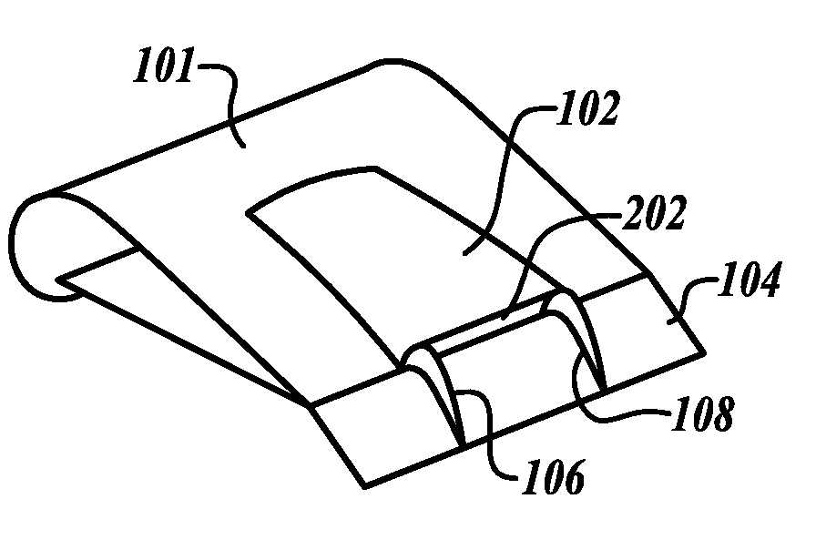
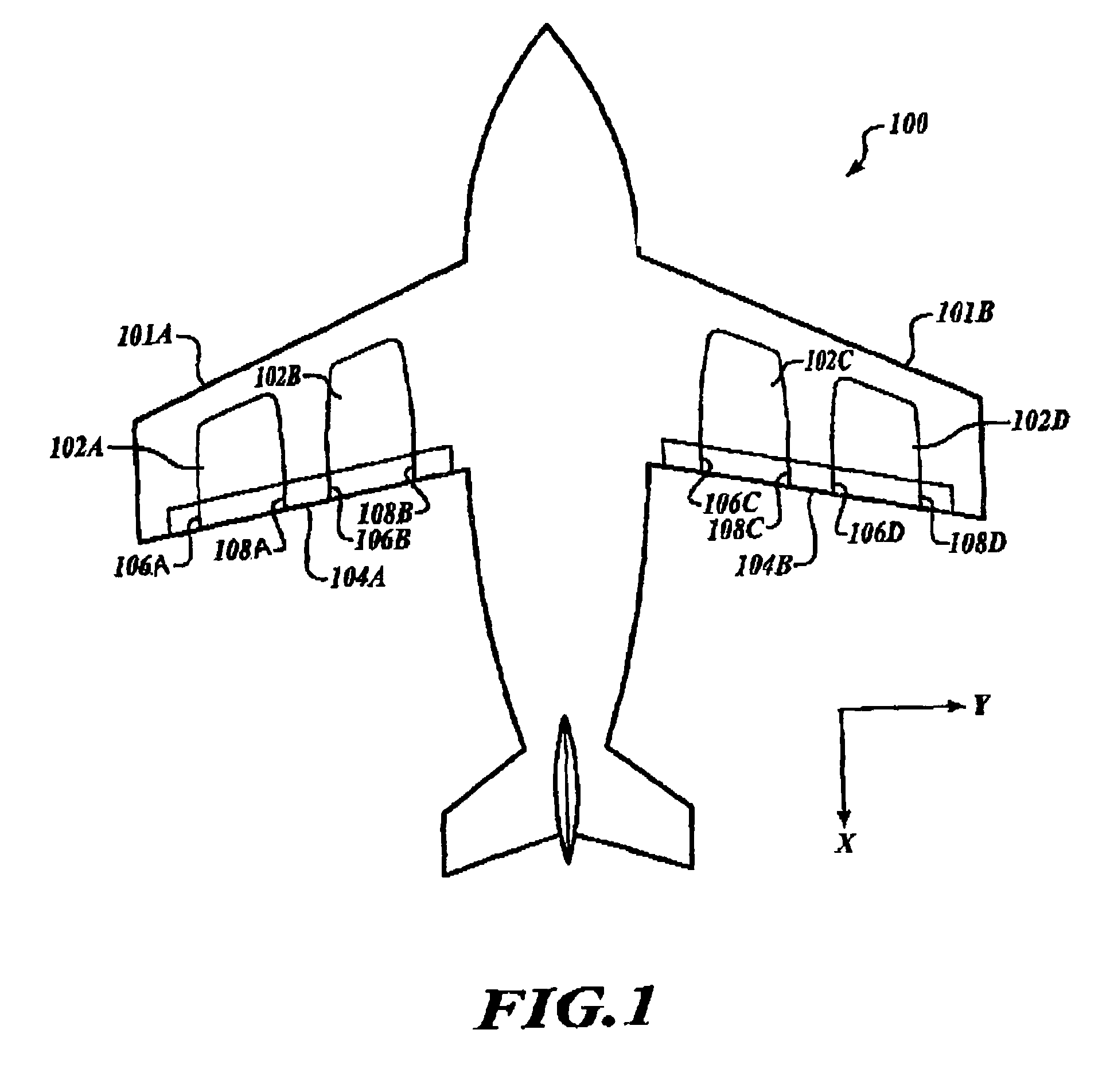
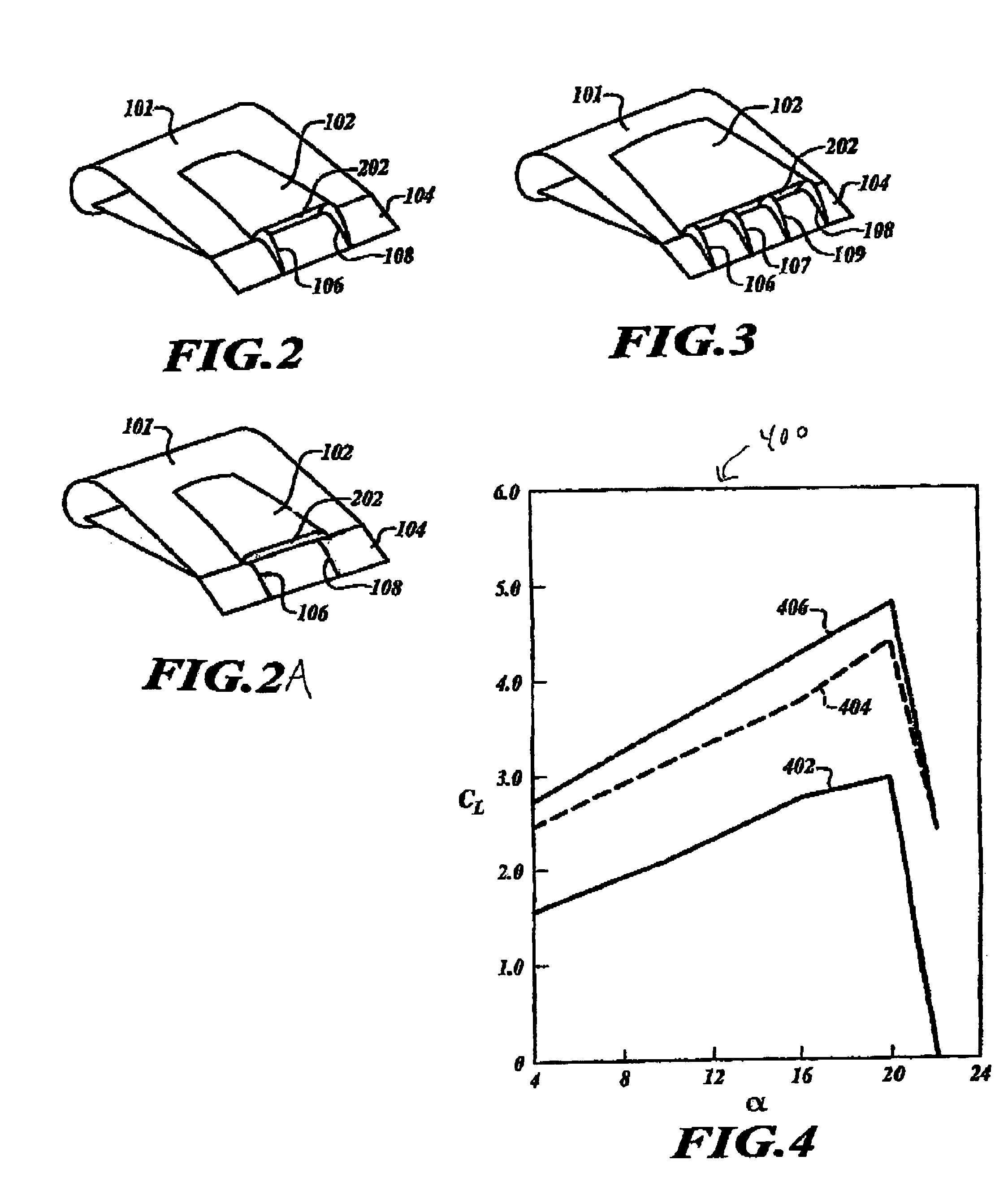
[0013]Generally speaking, the amount of lift produced along a surface of an aircraft can be increased by improving the flow of air over the surface. Especially in the case of STOL aircraft designed to exploit the Coanda Effect, lift can be reduced by three-dimensional effects whereby air flowing across an airfoil detaches from the surface of the aircraft. By restricting the three-dimensional effects of airflow and instead encouraging two-dimensional flow across the surface, the Coanda Effect along the surface is suitably increased, thereby resulting in increased lift.

[0014]One way to reduce three-dimensional airflow...


PUM


Abstract

Lift produced by an airfoil of an aircraft is increased by suppressing fluid detachment from the surface of the airfoil. An engine cowling extends outwardly from the surface of the airfoil that has an exit plane configured for directing exhaust gases toward a rear of the aircraft. Fences extending outwardly from the surface and proximate to the exit plane of the engine cowling are configured to guide the exhaust gases along at least a portion of the airfoil surface, thereby restricting spanwise movement of the gases and increasing the Coanda Effect exhibited by the gases, thereby increasing the amount of lift produced along the surface of the airfoil. Such techniques may be used in short take-off and landing (STOL) aircraft.

Description

TECHNICAL FIELD[0001]The embodiments described herein generally relate to producing lift in an aircraft, and more particularly relate to methods and apparatus for increasing engine-powered lift produced along a surface of an aircraft.BACKGROUND[0002]Scientists and engineers continue to seek improvements in all areas of aircraft performance. Recent military campaigns, for example, have demonstrated an increased need for improved short takeoff and landing (STOL) performance to allow aircraft to operate in environments where modern airports and other landing facilities may not be available. In particular, it is desirable to create aircraft that are able to takeoff and / or land even on short runways.[0003]One way to improve STOL performance is to increase the amount of lift produced along the airfoil surfaces of the aircraft. By increasing the lift capability of each wing, for example, the aircraft can become airborne at a lower airspeed, thereby reducing the length of runway needed for ...

Claims


Application Information

Patent Timeline
Patent Type & Authority Patents(United States)
IPC IPC(8): B64C21/04
CPCB64C3/58B64C7/00B64C9/38B64C21/04Y02T50/166B64C2230/04Y02T50/10
Inventor SHMILOVICH, ARVINYADLIN, YORAMGREGG, III, ROBERT D.CLARK, ROGER W.
Owner THE BOEING CO
Why Eureka
Try Eureka