Multi-axis pivoting detent joint assembly for an exterior vehicle mirror

a detent joint and vehicle mirror technology, applied in the direction of rod connections, couplings, machine supports, etc., can solve the problems of premature wear and tear of the joint, the degree of misalignment between the two detent surfaces, and the loosening of the detent joint, so as to improve the durability of the teeth

Inactive Publication Date: 2011-02-01
LANG MEKRA NORTH AMERICA LLC
View PDF38 Cites 18 Cited by
  • Summary
  • Abstract
  • Description
  • Claims
  • Application Information

AI Technical Summary

Benefits of technology

[0021]In a further embodiment, the rounded teeth include a metal coating to harden and enhance the durability of the teeth.

Problems solved by technology

However, manufacturing variances for large exterior vehicle mirror assemblies typically result in some degree of misalignment between the two detent surfaces when mounted to the vehicle.
This, however, leads to line and point contact location that create premature wear and tear on the joint.
This wear will eventually cause the detent joint to loosen over time from vibration.
Eventually, the joint will no longer hold the mirror in position.
In other cases, the mirror assembly system will not accommodate misalignment and results in poor or limited detent performance when mounted to the vehicle.

Method used


Image

  • Multi-axis pivoting detent joint assembly for an exterior vehicle mirror
  • Multi-axis pivoting detent joint assembly for an exterior vehicle mirror
  • Multi-axis pivoting detent joint assembly for an exterior vehicle mirror

Examples


Embodiment Construction

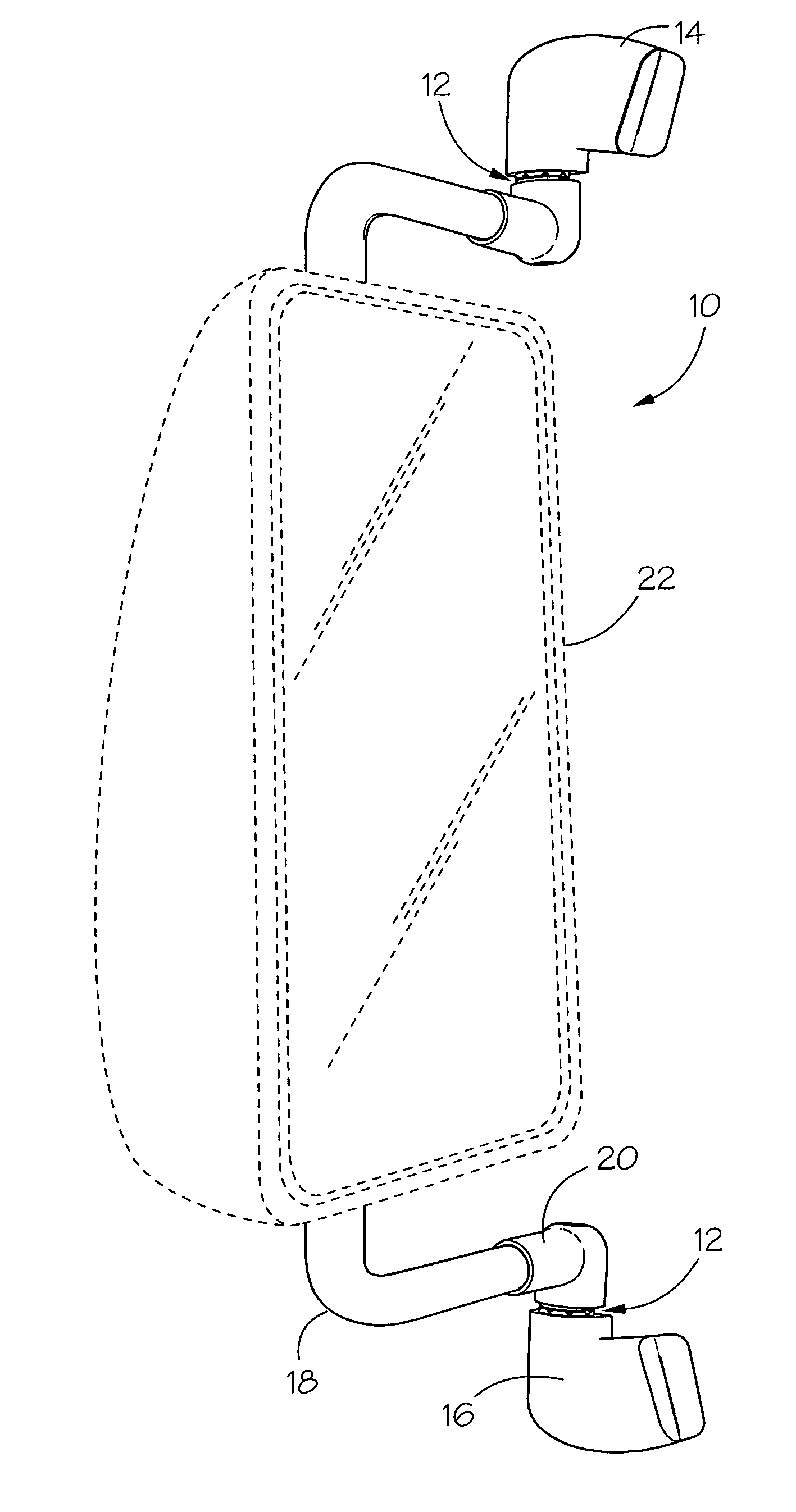
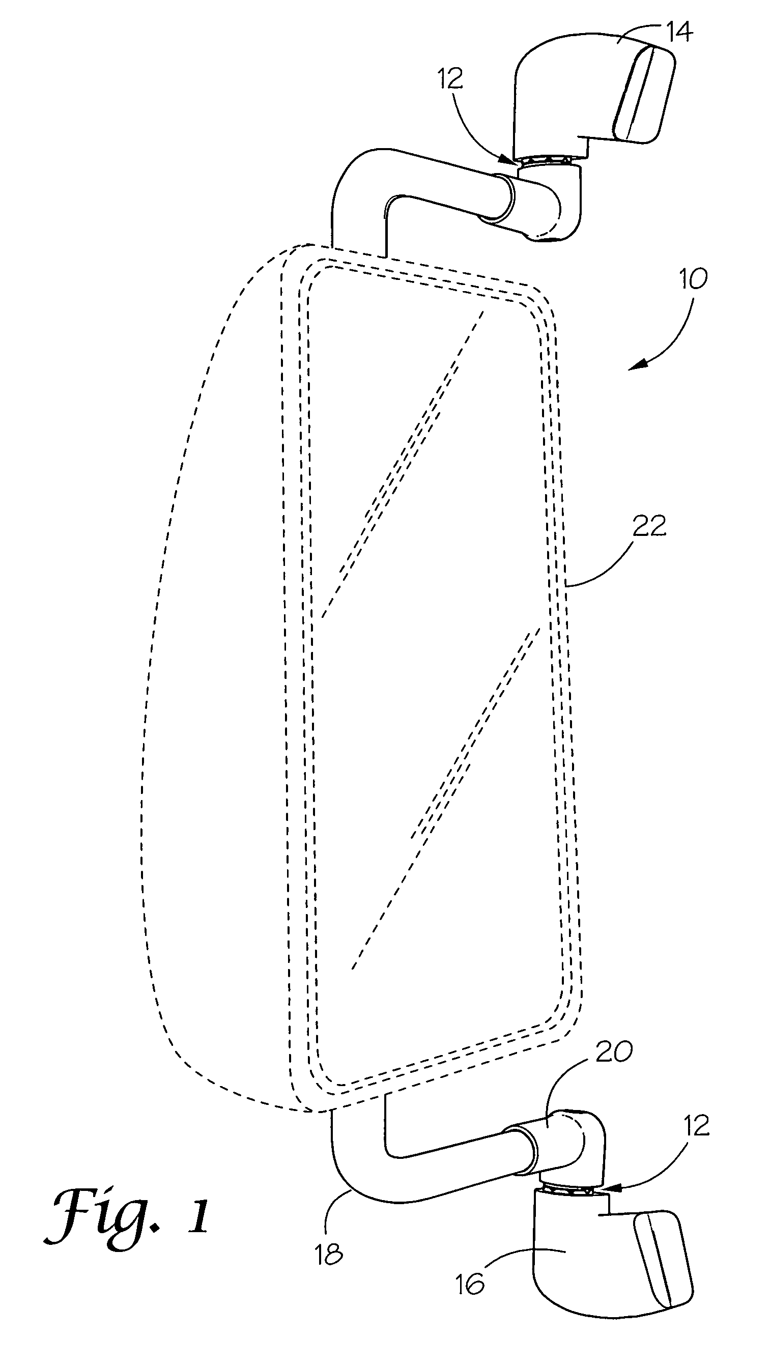
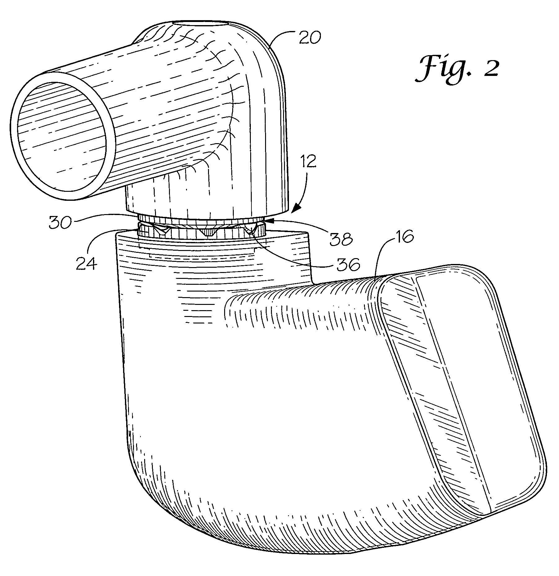
[0032]With reference to the drawings, the invention will now be described in more detail. Referring to FIGS. 1 and 2, an external vehicle mirror assembly, designated generally as 10, is shown which includes a multi-axis pivoting detent joint, designated generally as 12, on both an upper mounting bracket 14 and lower mounting bracket 16. Mounting brackets 14 and 16 are generally identical and the following detailed description in regard to mounting bracket 16 applies equally to mounting bracket 14. Further, while the illustrated embodiment shows both an upper and lower mounting bracket 14 and 16, it is understood that various alternative mirror assembly designs that hang from a single upper mounting bracket or rest on a single lower mounting bracket are considered within the spirit and scope of the present invention. Incorporating both an upper and lower mounting bracket may not be required for practicing the present invention and is dependent upon the qualified design for a given ve...


PUM


Abstract

A mirror assembly comprising a mounting bracket for attachment to a vehicle exterior; a first pivot plate on the mounting bracket having a concave upper surface with a series of grooves formed therein; a support arm pivotally carried on the first pivot plate of the mounting bracket; and, a second pivot plate carried by the support arm having a base surface with a plurality of protruding teeth engaging the grooves in the first pivot plate so that a pivot gap is defined between the upper surface of the first pivot plate and the base surface of second pivot plate; whereby the pivot gap allows the teeth to both pivot and slide in the grooves of the first pivot plate so that the support arm is pivotal in a multi-axis arrangement with the mounting bracket to accommodate misalignment between the mounting bracket and the support arm during installation on a vehicle.

Description

CROSS REFERENCE TO RELATED APPLICATION[0001]This application claims priority from U.S. Provisional Application filed Jan. 2, 2008 under Application No. 61 / 009,760.BACKGROUND OF THE INVENTION[0002]1) Field of the Invention[0003]The present invention relates to exterior vehicle mirror assemblies, and more particularly, to a detent joint for large commercial vehicle mirror assemblies that involves rounded cooperating surface geometries to allow for multi-axis movement to accommodate misalignment between a mounting bracket and support arm when mounted to the vehicle, while maintaining the proper detent function to hold the mirror assembly in a desired position.[0004]2) Description of Related Art[0005]Exterior mirror assemblies are known to include a detent connection joint between a mounting bracket attached to the vehicle and a support arm carrying the mirror head so that the mirror can be selectively positioned and held in place. However, manufacturing variances for large exterior veh...

Claims


Application Information

Patent Timeline
Patent Type & Authority Patents(United States)
IPC IPC(8): A47G1/24B60R1/02
CPCB60R1/0605Y10T403/32057Y10T403/32073Y10T403/32368
Inventor COURBON, EMMANUEL
Owner LANG MEKRA NORTH AMERICA LLC
Why Eureka
Try Eureka