Mechanical seal device
a mechanical seal and sealing device technology, applied in the direction of engine seals, mechanical apparatus, engine components, etc., can solve the problems of difficult part management and control, difficult to provide an effect of cooling to a source of sliding frictional heat, and increase the danger of contaminating oil or chemical fluid located in the outer circumferential side with quenching fluid, etc., to achieve the effect of easy replacement of parts in the disassembly of the mechanical seal devi
- Summary
- Abstract
- Description
- Claims
- Application Information
AI Technical Summary
Benefits of technology
Problems solved by technology
Method used
Image
Examples
first embodiment
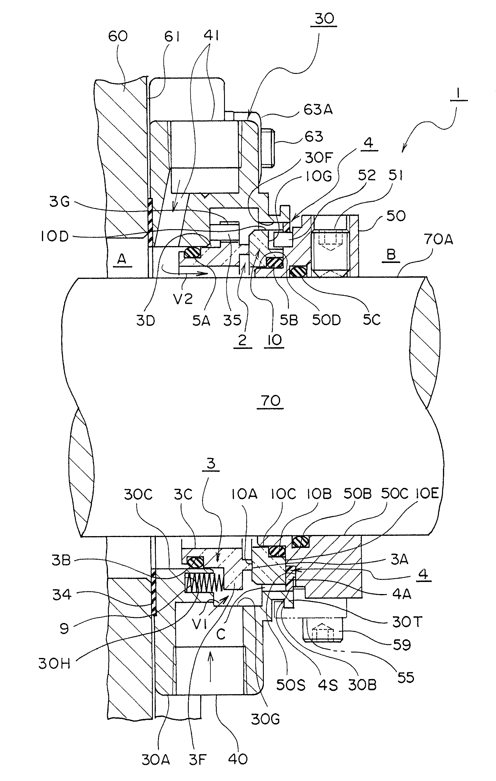
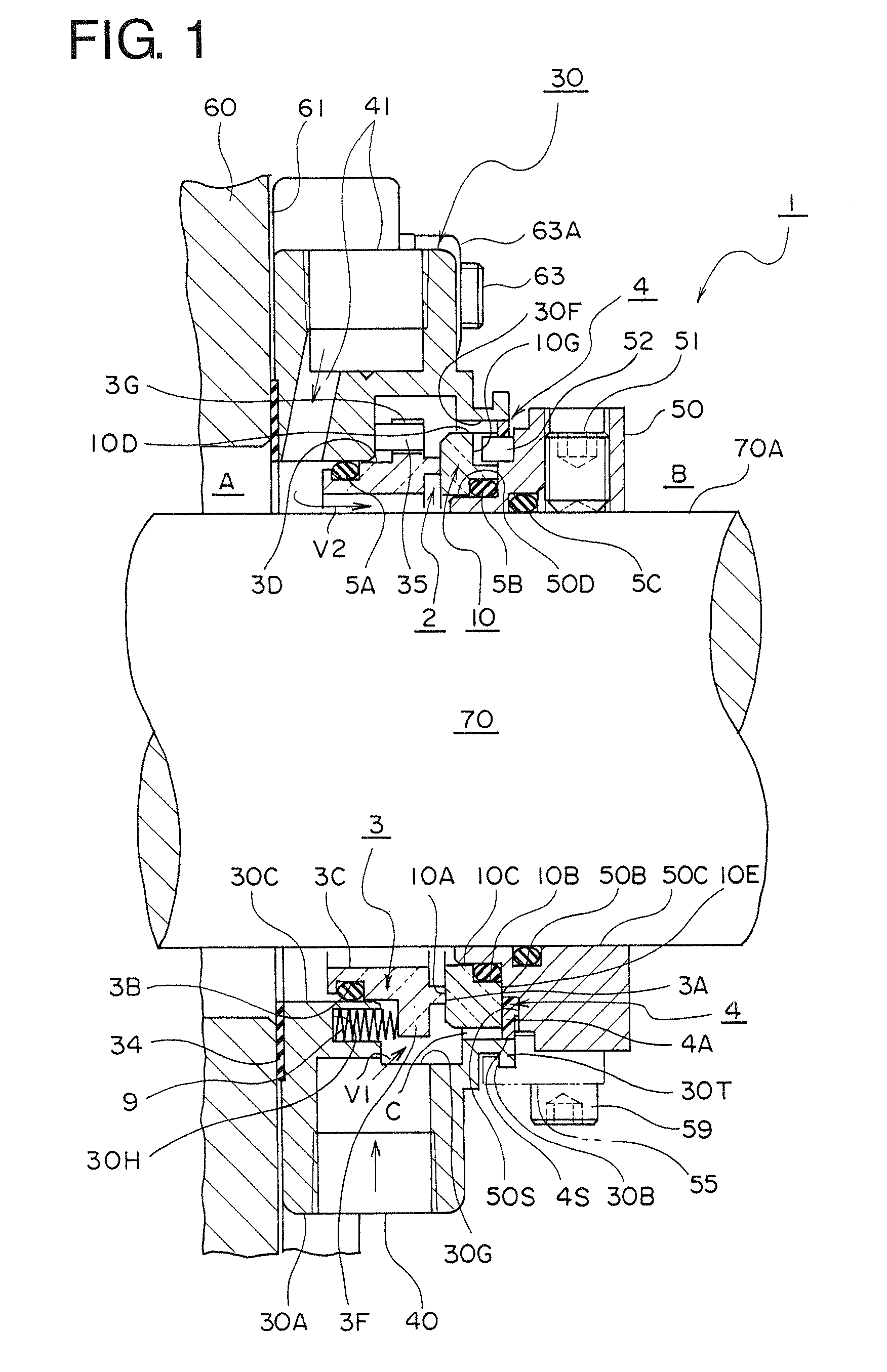
[0033]FIG. 1 shows a mechanical seal device 1 as a first embodiment relative to the present invention. There is disposed a rotary shaft 70 extending through a shaft bore hole of an apparatus main body (casing) 60. The mechanical seal device 1 is mounted onto an outboard wall face 61 via a seal cover 30 wherein the outboard wall face 61 is located around the circumference of the shaft bore entrance of the apparatus main body 60. In the apparatus main body 60, there are four pieces of stud bolts disposed at four different places along the circumference of the outboard wall face 61. The rotary shaft 70 is supported in freely rotatable a manner by means of a bearing, not shown, which is mounted to the shaft bore. A space within the bore hole of the apparatus main body 60 corresponds to an inboard space A while the opposite (outward) the apparatus main body 60 with respect to the mechanical seal device 1 corresponds to an outboard B.
[0034]Further details on the mechanical seal device 1 w...
second embodiment
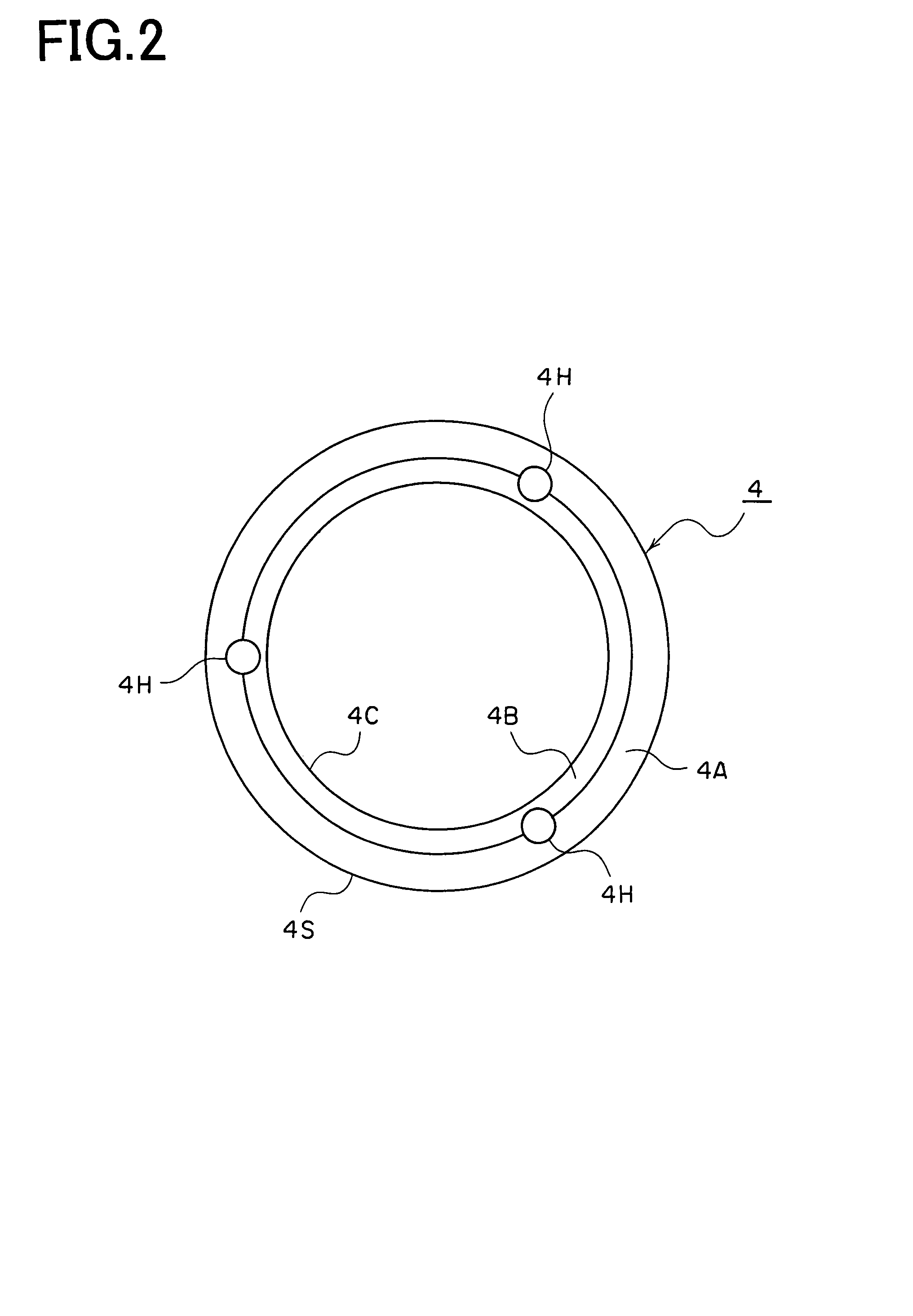
[0045]FIG. 3 shows a cross sectional view of a portion of packing 4 as a second embodiment related to the present invention. This packing 4 disposes discharge means 4T on ring-shaped side wall thereof in which radially extending projected portions and radially extending recessed portions are lined up alternately along the circumference. The discharge means 4T consists of projected portions 4T1 and recessed portions 4T2. Other names are the same as those of reference numerals used in FIG. 2, i.e., seal portion 4A, installation portion 4B, fit contact face 4C and seal contact face 4S. This discharge means 4T pushes the quenching liquid V1 (refer to FIG. 1) in the small clearance C back to inside the annular groove 30G and prevents contaminants attached on the seal contact face 4S from wearing the seal contact face 4S. The discharge means 4T, at the same time, pushes away the contaminants contained in the quenching liquid V1 toward annular groove 30G side, thereby improving seal abilit...
third embodiment
[0046]FIG. 4 is a cross sectional view of a portion of packing 4 as a third embodiment related to the present invention. This packing 4 has approximately the same form as that shown by the same reference numerals in FIG. 2. A difference resides in that there is disposed a discharge means 4S1 of a spiral groove design on the quenching liquid V1 (refer to FIG. 1) side of the seal contact face 4S, thereby pushing back the quenching liquid V1 enhancing seal ability of the packing 4. This packing 4 is made of Fluoride Resin.
[0047]In the mechanical seal device 1 thus constructed, the quenching liquid V1 can provide an effective cooling against sliding frictional heat generated in the mechanical seal 2 and can prevent an occurrence of thermal damage or squeaking noise at the relative seal faces 3A, 10A. The cooling effect due to the quenching liquid V1 within the annular groove 30G enhances a seal performance of the respective relative seal faces 3A, 10A. Unlike the prior art, as no sleeve...
PUM
 Abstract
Description
Claims
Application Information
 - R&D
- Intellectual Property
- Life Sciences
- Materials
- Tech Scout
- Unparalleled Data Quality
- Higher Quality Content
- 60% Fewer Hallucinations
Browse by: Latest US Patents, China's latest patents, Technical Efficacy Thesaurus, Application Domain, Technology Topic, Popular Technical Reports.
© 2025 PatSnap. All rights reserved.Legal|Privacy policy|Modern Slavery Act Transparency Statement|Sitemap|About US| Contact US: help@patsnap.com


