Infusion set

a technology of infusion set and infusion needle, which is applied in the direction of infusion needle, other medical devices, catheters, etc., can solve the problems of inability to properly protect the cannula, the injection process is often unpleasant for users, and the inability to accurately use the device, so as to reduce the danger of users incorrectly using the devi

Active Publication Date: 2011-02-01
ROCHE DIABETES CARE INC
View PDF12 Cites 511 Cited by
  • Summary
  • Abstract
  • Description
  • Claims
  • Application Information

AI Technical Summary

Benefits of technology

[0009]In some embodiments, the protective element can surround the tip of the cannula partially or completely or can surround the entire cannula, or a needle provided for inserting the cannula as the case may be, in order to guarantee the protective function. Furthermore, an operating element is provided whereby the cannula or needle and cannula can be moved out of the protective element, in order to insert the cannula into the tissue. In some embodiments, if a needle is used, it is preferable if, once the cannula has been inserted, the needle can be moved back into the protective element again, using the operating element or also automatically, e.g., using a spring mechanism, in order to also minimise or rule out the danger of injury once the cannula has been inserted.
[0041]Advantageously, at least one securing element is provided on the cannula inserting device, said securing element preventing a triggering element from being unintentionally operated. Such a securing element may be designed such that it has to be removed from the cannula inserting device or moved to a safety-release position on the cannula inserting device, in order to be able to operate the triggering element at all. The securing element can be designed as a securing cap which at least partially and, preferably, approximately completely surrounds the triggering element and protects it from being unintentionally touched and thus from being undesirably triggered. Furthermore, the securing element can also be designed as a device for blocking or arresting the triggering element which has to be shifted first before in order to be able to operate the triggering element. It is then advantageous to design the securing element such that it cannot simply be moved by an unintentional touch or a jolt, but rather can only be moved by a pressing movement between two fingers to a position in which the triggering element can be operated. The securing element can then be designed such that it either requires a constant pressure or drag in order to move the triggering element to the safety-release position or remains in the safety-release position once a safety-release process has been performed and locks in, such that the triggering element can be operated once the safety has been released.

Problems solved by technology

Here, too, the cannula is relatively unprotected once inserted, and can easily be inadvertently removed.
A cannula comprising a needle is inserted, wherein at the same time as the cannula is inserted, an arrangement connected fixedly to the cannula and having an adhesive underside is applied to the skin, which makes the injection process, which is often unpleasant for the user, additionally difficult.
In the known devices, the cannula is either relatively unprotected against being unintentionally removed, a drag force acts on the cannula inserted into the tissue even as the needle is removed from the cannula, or an additional device has to be moved together with the cannula during the injection process, which makes positioning it exactly difficult.

Method used


Image

  • Infusion set
  • Infusion set
  • Infusion set

Examples


first embodiment

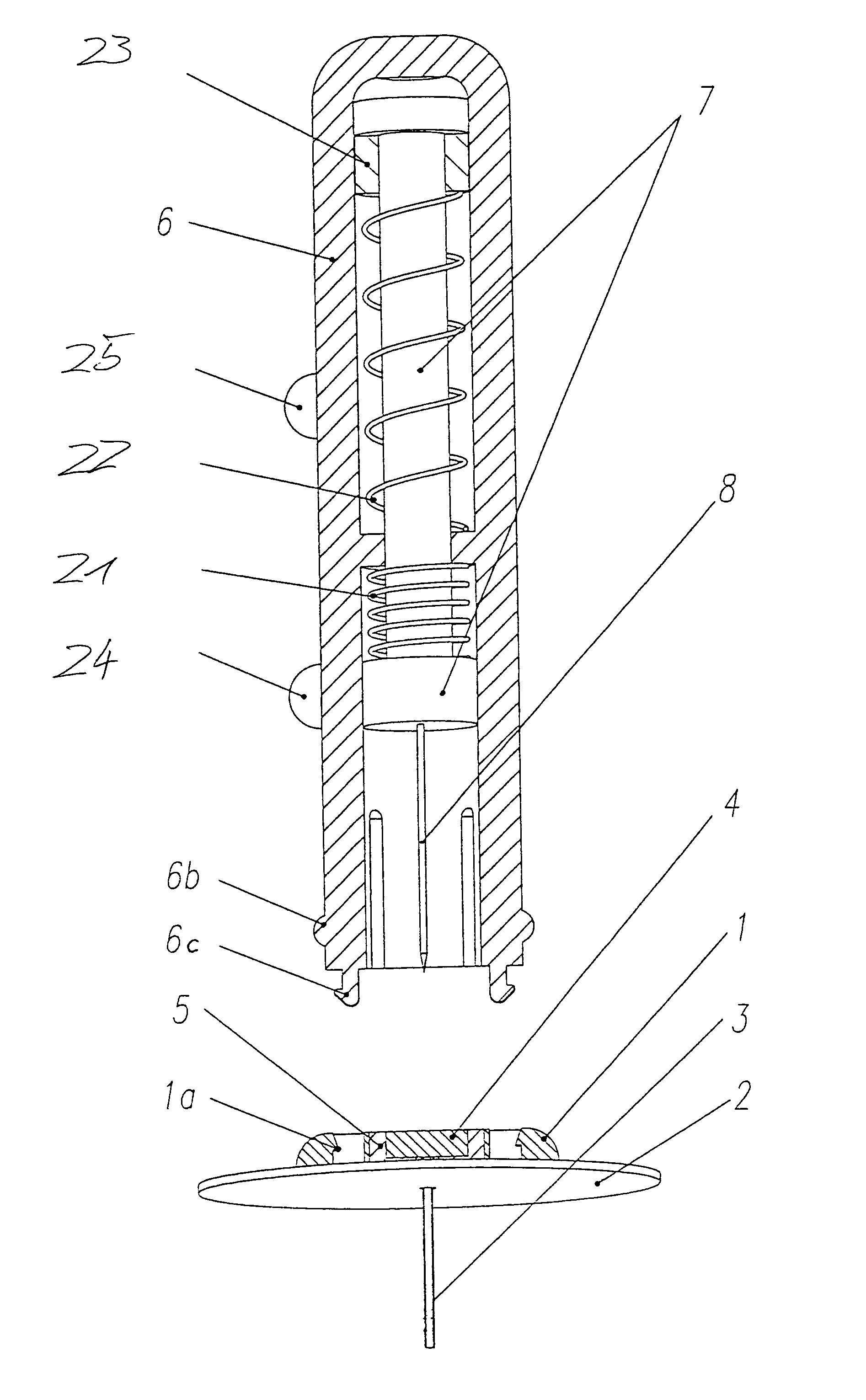
[0081]FIG. 13 shows an automatic cannula inserting and restoring device, in its initial state before a cannula 3 on a cannula sub-assembly 35 has been inserted using a guiding needle 8. The cannula inserting device comprises a connector sleeve or guiding element 38 which has connector elements 39 at its lower end, in order for example to be fastened on a foundation or base body 1, as shown for one of the embodiments in the figures above. Said connector elements 39 for connecting the connector sleeve 38 to a predetermined base body comprise for example latching tongues 39a and other connecting elements (not shown). Within the connector sleeve 38, the guiding sleeve 33 is provided with tongues 33a, 33b and 33c protruding inwards from it. The tongues 33a to 33c are arranged at various positions in the axial direction of the guiding sleeve 33 and can be arranged as individual protruding elements or also over a large part of the circumference of the guiding sleeve 33. The tongues can als...

second embodiment

[0086]FIG. 16 shows an automatic cannula inserting and restoring device in its initial state, comprising a connector sleeve 38 which is connected to a foundation body 1. A triggering button 37 passes into the triggering sleeve 37a arranged within the connector sleeve 38. The triggering sleeve 37a recesses and lower and upper chamfers on the inner side along its axial direction, using which a lower and an upper slaving ring 32a and 32b can be uncoupled when the triggering sleeve 37a is shifted axially, in order to expel the guiding needle 8, together with the cannula 3 arranged around it and the corresponding cannula sub-assembly 35, out of the connector sleeve 38 and to then retract the guiding needle 8 out of the cannula 3 and the cannula sub-assembly 35, as will be described below.

[0087]The lower slaving ring 32a abuts a stopper sleeve 36 and is held in position by the stopper sleeve 36 against the pressure of the spring 31. The spring 31 presses on the upper side against the uppe...


PUM


Abstract

A device for inserting a cannula into tissue, including a cannula, a protective element which can accommodate said cannula, an operating element for moving the cannula out of the protective element, and a holder fixedly connected to the cannula. The invention encompasses a system for connecting a liquid supply to the cannula.

Description

CROSS-REFERENCE TO RELATED APPLICATIONS[0001]This application is a Continuation of International Patent Application PCT / CH02 / 00186, filed on Apr. 3, 2002, which claims priority to German Application No. 101 17 285.0, filed on Apr. 6, 2001 and German Application No. 201 10 059.2, filed on Jun. 19, 2001.BACKGROUND OF THE INVENTION[0002]The present invention relates to an infusion set, in particular to a device for inserting a cannula into tissue, for example skin tissue, fatty tissue or muscle tissue, and to a device for supplying a liquid via the cannula into the tissue.[0003]A device for inserting a catheter comprising a needle is known from EP 0 451 040 A1, wherein a cover is provided which may be pushed together over the needle. The catheter can thus be inadvertently removed even by small drag forces acting on the catheter, and lies open, relatively unprotected, at the injection point; see FIG. 1 in EP 0 451 040 A1.[0004]EP 0 290 176 A1 discloses a device for inserting a cannula c...

Claims


Application Information

Patent Timeline
Patent Type & Authority Patents(United States)
IPC IPC(8): A61M5/178A61M5/34A61M5/158A61M5/32A61M25/00A61M25/02A61M25/06A61M39/02A61M39/10
CPCA61M5/158A61M39/02A61M25/0612A61M5/3243A61M25/0097A61M25/02A61M2005/1587A61M39/1011A61M2005/1581A61M2005/1585
Inventor HUNN, MARCELLINIGER, JURGDENOTH, PATRIKOESCH, MARCBUTIKOFER, MARKUSZIHLMANN, RUDOLFSCHEURER, SIMON
Owner ROCHE DIABETES CARE INC
Why Eureka
Try Eureka