

Temperature detection circuit
a technology of temperature detection circuit and operating voltage, which is applied in the direction of heat measurement, pulse technique, instruments, etc., can solve the problems of higher operating voltage of the lowest operating voltage of the temperature detection circuit, so as to suppress the rise of the lowest operating voltage
- Summary
- Abstract
- Description
- Claims
- Application Information
AI Technical Summary
Benefits of technology
Problems solved by technology
Method used
Image


Examples
embodiment 1
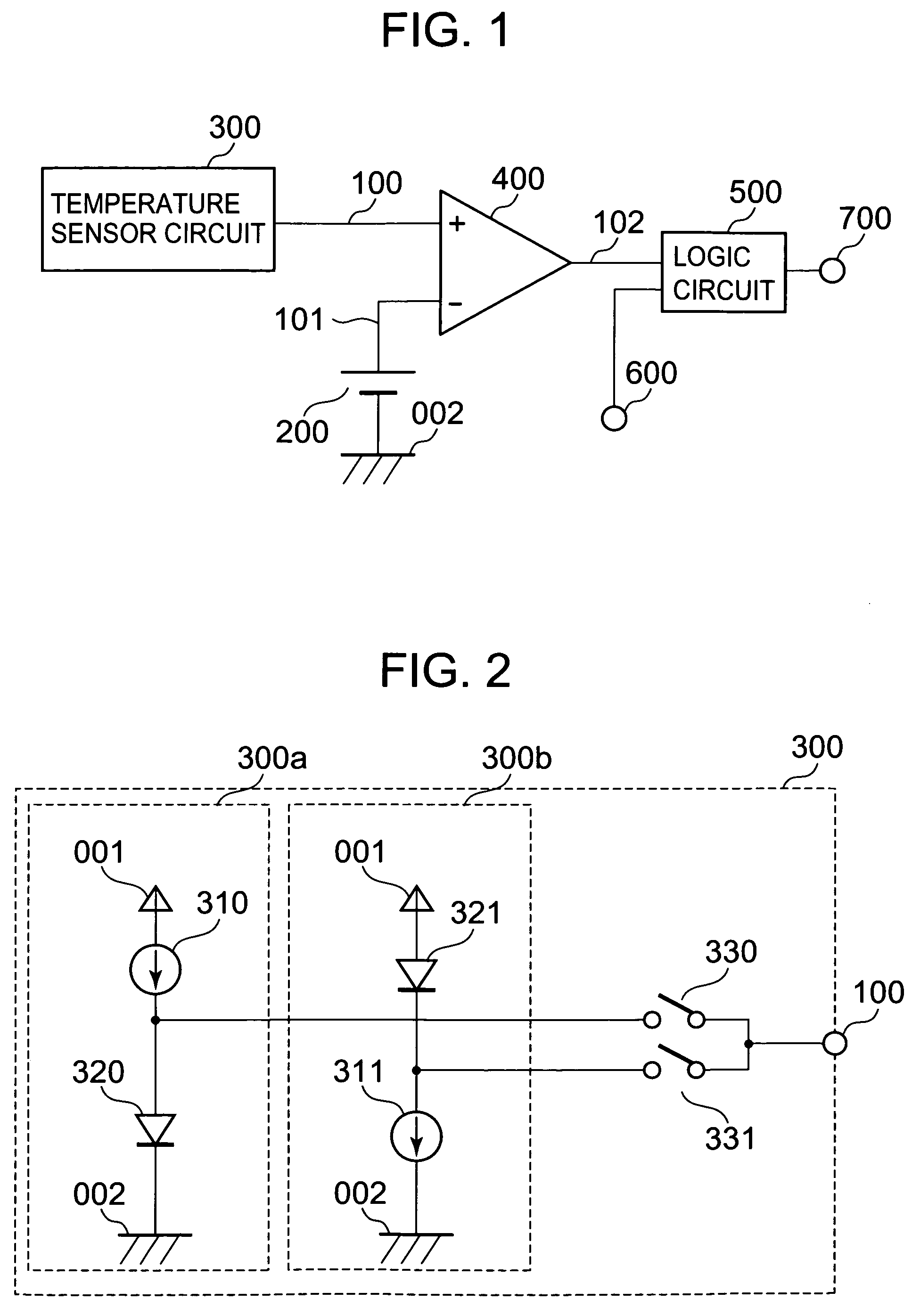
[0040]FIG. 1 illustrates a configuration of a temperature detection circuit according to a first embodiment of the present invention. FIG. 2 is a circuit diagram of an exemplary temperature sensor circuit 300 in the temperature detection circuit according to the first embodiment.
[0041]The temperature detection circuit according to the first embodiment includes a positive power supply terminal 001, a negative power supply terminal 002, a reference voltage circuit 200, a temperature sensor circuit 300, a comparator 400, a logic circuit 500, an input terminal 600, and an output terminal 700.
[0042]A negative pole of the reference voltage circuit 200 is connected to the negative power supply terminal 002 and a positive pole of the reference voltage circuit 200 as an output terminal 101 is connected to an inverting input terminal of the comparator 400. A reference voltage from the reference voltage circuit 200 is adjusted by changing the size of elements such as a resistor and a MOS trans...
embodiment 2
[0054]FIG. 5 is a circuit diagram of a temperature sensor circuit in a temperature detection circuit according to a second embodiment of the present invention. A temperature sensor circuit 300 of the temperature detection circuit according to the second embodiment includes constant current sources 310 and 311, a diode 320, and switches 332 and 333.
[0055]One end of the constant current source 310 is connected to a positive power supply terminal 001 and the other end of the constant current source 310 is connected to the switch 332. One end of the constant current source 311 is connected to a positive power supply terminal 001 and the other end of the constant current source 311 is connected to the switch 333. A cathode side electrode of the diode 320 is connected to a negative power supply terminal 002, and an anode side electrode of the diode 320 is connected to the other end of the switch 332, the other end of the switch 333, and an output terminal 100.
[0056]Next, operation of the ...
PUM
 Abstract
Description
Claims
Application Information