Lens driving device

a driving device and lens technology, applied in the direction of printers, instruments, cameras, etc., can solve the problems of uneven length from the bottom of the lower casing, uneven maximum displacement in the operation difficulty in precisely adjusting the maximum displacement of the lens device, so as to eliminate the uneven maximum displacement and less on the accuracy of components

Active Publication Date: 2011-02-01
MICRO WIN TECH +2
View PDF4 Cites 6 Cited by
  • Summary
  • Abstract
  • Description
  • Claims
  • Application Information

AI Technical Summary

Benefits of technology

[0020]By providing components for limiting the maximum displacement of the lens on the lower position of the lens driving device when stacking all components, the number of high-accuracy components required may be reduced, and the unevenness of the maximum displacement of the lens holder with respect to the base may also be eliminated.
[0021]Accordingly, not only the maximum displacement of the lens may be precisely controlled, but the rising costs of relevant components may also be avoided for the present invention.
[0025]In this way, even though the base area is decreased, the spacer may still be placed precisely on the base, to achieve device miniaturization and weight reduction.

Problems solved by technology

For this reason, if the accuracy and completeness of the stacked components are not precisely controlled, there may be the problem of uneven length from the bottom of the lower casing 56, as the base, to the front-end of the lens holder 52.
The unevenness of length results in the unevenness of maximum displacement in the operation of the lens device.
Therefore, with current method, it is difficult to precisely configure the maximum displacement of the lens device.
The aforementioned drawback is a serious problem to the miniaturization of the lens device.
Moreover, the requirement of maintaining high accuracy for dimensions of all components in the lens device may incur higher costs as well as more complications to manipulate the relevant components.

Method used


Image

  • Lens driving device
  • Lens driving device
  • Lens driving device

Examples


Embodiment Construction

[0033]The present invention will now be described with detailed embodiments. The following embodiments do not limit the invention relevant to the scope of claims. Also, all combination of the features described in the embodiments are not necessarily required in the solution means of the present invention.

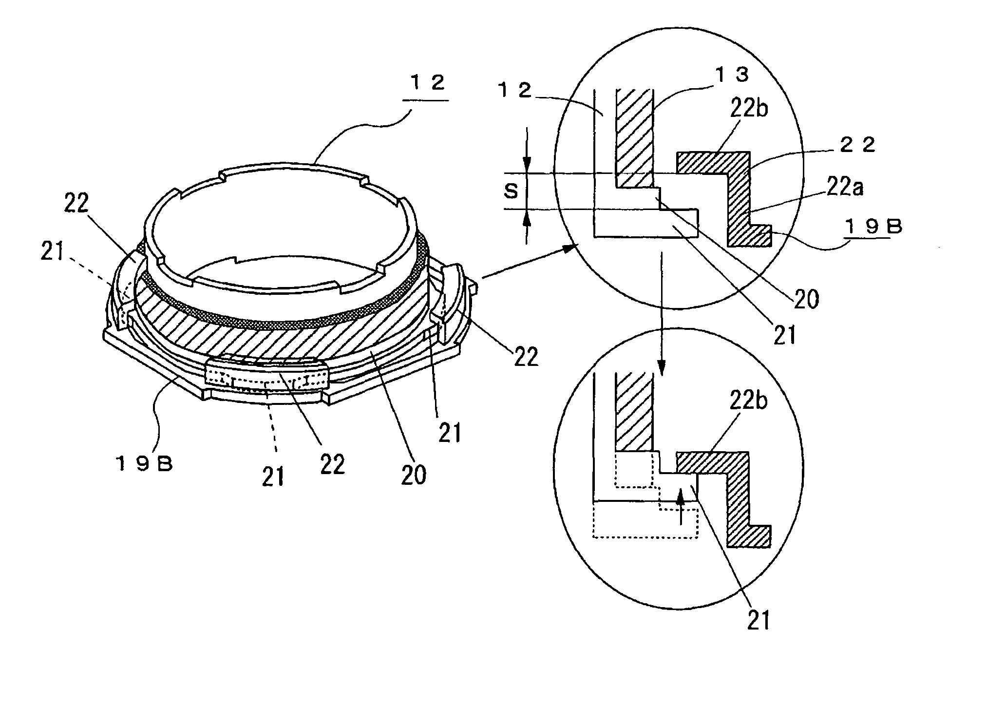
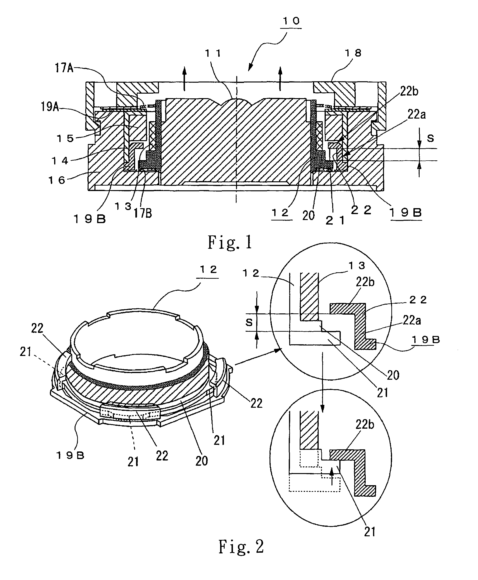
[0034]FIG. 1 is a cross-section view of a lens driving device 10 in accordance with the embodiment of the present invention. FIG. 2 is a view explicitly illustrating the relative position of the first protrusion and second protrusion of the present invention. FIG. 3 is an exploded perspective view of the lens driving device 10 of the present invention.

[0035]The lens driving device 10 comprises at least one lens 11, a lens holder 12, a driving coil 13, a yoke 14, a magnet 15, a lower casing 16 served as a base, an upper spring plate 17A, a lower spring plate 17B, an upper casing 18, an upper spacer 19A, and a lower spacer 19B.

[0036]Lower spacer 19B is a component equivalent to the sp...


PUM


Abstract

A lens driving device is provided to reduce a number of required high-accuracy components and also eliminate the unevenness of maximum displacement of a lens holder with respect to a base. An outer edge of a lower spring plate is clamped by a lower casing served as a base and a lower spacer. A first protrusion is formed on a sidewall of the lens holder and protruding outward therefrom. A second protrusion protruding toward the lens holder is formed on an inner circumference of the lower spacer and extends to a position above and separating from the first protrusion by a distance S. The first protrusion props against the second protrusion when the lens holder is moved toward an imaged-object side and reaching a displacement of the distance S.

Description

FIELD OF THE INVENTION[0001]The present invention relates to a lens driving device for a camera; more particularly, to a lens driving device with spring plates elastically supporting a lens holder holding object lenses on a base.DESCRIPTION OF RELATED ART[0002]Recently, with the increase in the pixel numbers of the camera installed inside a mobile device, such as a cell phone, the development of the camera is moving toward high-performance functions, such as zoom processing or fine-moving-distance processing. With respect to the lens system installed inside the current digital device, the industry dedicates not only in the research of fixed-focal type lens system, but also in the research of vari-focal type lens system. As shown in FIG. 6, the lens driving device 50 employing the voice coil motor is generally used in the case of vari-focal type lens systems (For example, please refer to the patent document 1 incorporated herein).[0003]As shown in FIG. 6, the lens driving device 50 c...

Claims


Application Information

Patent Timeline
Patent Type & Authority Patents(United States)
IPC IPC(8): G02B7/02
CPCG02B7/08G03B3/10
Inventor HAGIWARA, KAZUYOSHI
Owner MICRO WIN TECH
Why Eureka
Try Eureka