Accessory mount for a firearm

Active Publication Date: 2011-02-08
ELZETTA DESIGN
View PDF12 Cites 15 Cited by
  • Summary
  • Abstract
  • Description
  • Claims
  • Application Information

AI Technical Summary

Benefits of technology

[0010]Therefore, an accessory can be secured to a firearm without the need for complex rail systems or other intermediate devices, while still providing for secure mounting of the accessory to the firearm. No removal, disman

Problems solved by technology

However, such rail systems can add significant weight to the firearm and also require

Method used


Image

  • Accessory mount for a firearm
  • Accessory mount for a firearm
  • Accessory mount for a firearm

Examples


Example

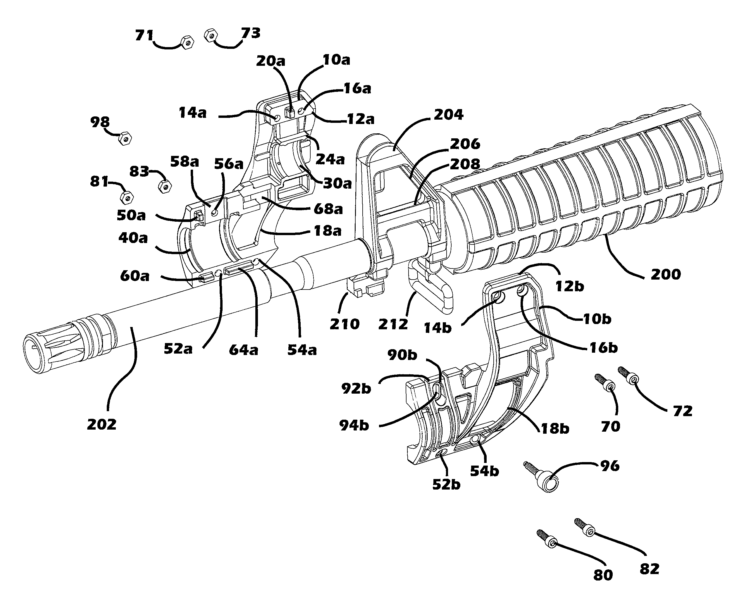
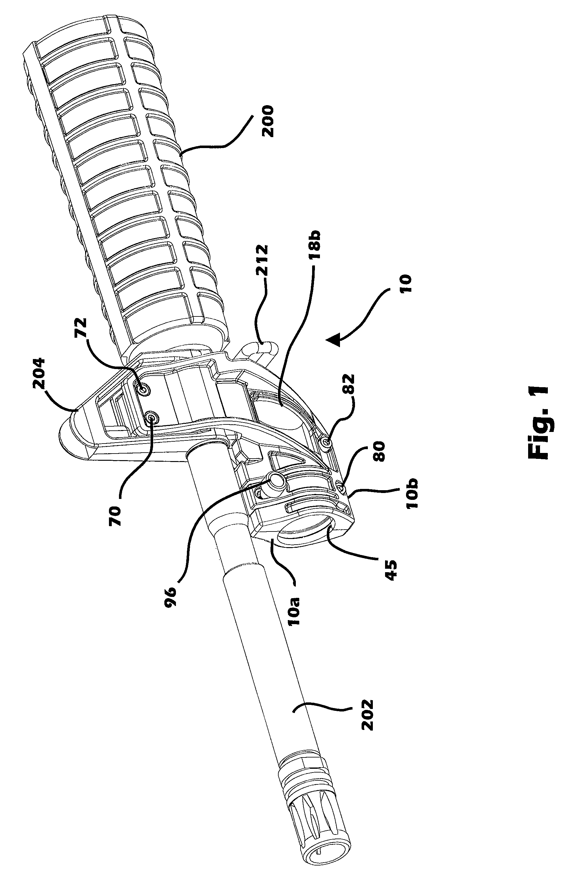
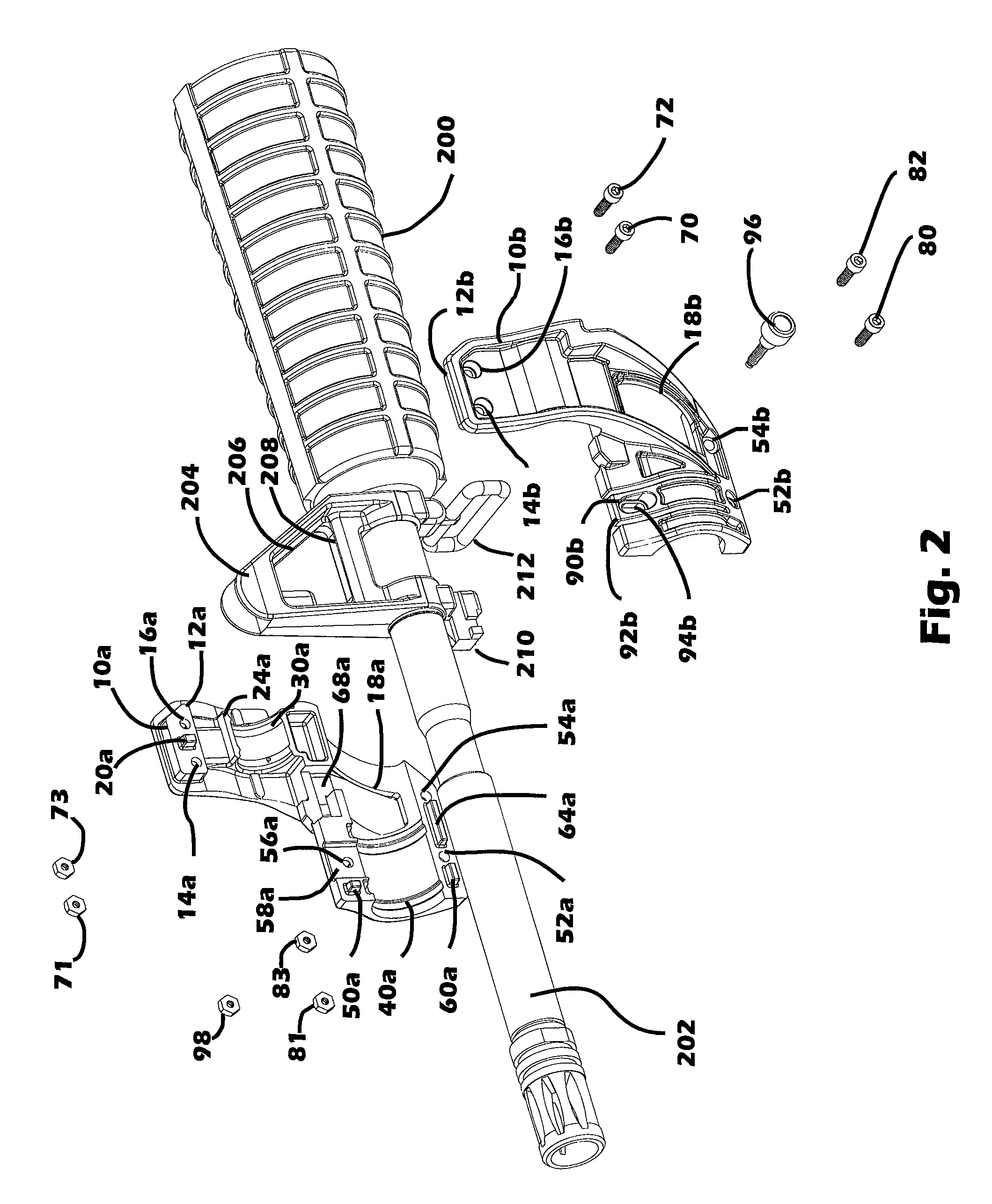
[0019]The present invention is an accessory mount for a firearm, and, more particularly, an accessory mount that engages the front sight of the firearm.

[0020]Referring now to FIGS. 1-4, an exemplary accessory mount 10 made in accordance with the present invention engages the front sight 204 of a firearm 200. In this example, and as shown in FIGS. 1-4, the exemplary accessory mount 10 is secured to a firearm 200 that is from the AR-15 family of firearms, which includes not only the AR-15 semiautomatic rifles manufactured and distributed by Colt Industries, Inc. of New York, N.Y. for civilian and sporting use, but also includes M-16 rifles and variants thereof that are used by U.S. and foreign militaries, along with similar firearms or “clones” distributed by other manufacturers. The firearm 200 includes a barrel 202, and the front sight 204 is positioned near the front end of the barrel 202. The front sight 204 has a generally trapezoidal shape and defines an aperture 206 therethroug...


PUM


Abstract

An accessory mount for a firearm that includes a barrel and a front sight located on the barrel comprises: a first section adapted to engage a first side of the firearm at the front sight and including a boss that extends into and is received in an aperture defined by and through the front sight; a second section adapted to engage a second side of the firearm at the front sight and including a boss that extends into and is received in the aperture defined by and through the front sight; and one or more fasteners that secure the first and second sections to one another; wherein the first and second sections collectively define a substantially cylindrical channel adapted to receive and secure an accessory below the barrel of the firearm.

Description

CROSS-REFERENCE TO RELATED APPLICATIONS[0001]The present application claims priority to U.S. Provisional Patent Application Ser. No. 60 / 959,386 filed on Jul. 14, 2007, the entire disclosure of which is incorporated herein by reference.BACKGROUND OF THE INVENTION[0002]In recent years, the increasing complexity of tactical operations and gear has generated a need for various accessories that are mounted to a firearm, including, for example, flashlights, scopes, laser sights, etc. Consequently, various mounts and mounting systems have been developed for securing such accessories to a firearm. For example, various rail systems are known in the art for securing accessories to a firearm. In such rail systems, rails or tracks are fixed to the barrel or stock of the rifle, with the accessories then being mounted to the rails or tracks. However, such rail systems can add significant weight to the firearm and also require multiple and / or complex fasteners that can add potential failure points...

Claims


Application Information

Patent Timeline
IPC IPC(8): F41G1/00F41G1/35
CPCF41C27/00F41G1/02F41G11/004
Inventor MARCUM, BRYAN T.BARNETT, DAVID L.
Owner ELZETTA DESIGN
Why Eureka
Try Eureka