System and method for managing emissions from diesel powered systems

a technology of diesel power system and management method, which is applied in the direction of electric control, machine/engine, point-of-use vehicles, etc., can solve the problems of inability of railroad dispatchers to make available the best-suited locomotive for a particular mission, affecting the efficiency of locomotives, and wasting tim

Inactive Publication Date: 2011-02-08
GE GLOBAL SOURCING LLC
View PDF19 Cites 43 Cited by
  • Summary
  • Abstract
  • Description
  • Claims
  • Application Information

AI Technical Summary

Problems solved by technology

Modern railroad locomotives are complex vehicles containing multiple operating systems including sophisticated computerized controls responsive to a large number of input variables.
A switcher locomotive may also spend a significant amount of time idling, whereas road locomotives must operate for long periods at high power levels.
Railroad mission requirements are affected by numerous variables including customer demand, weather, equipment availability, personnel availability, government regulations, etc., and it is often impossible for a railroad dispatcher to make available the best-suited locomotive for a particular mission.
As a result, a locomotive originally assembled with the configuration suited for an initial intended mission will provide less-than-optimal configuration when placed into service for another and different mission, and typically the best a dispatcher is able to do is to provide a locomotive that presents a good compromise of capabilities to meet a range of different (and often competing) mission requirements.
Additionally, locomotives do not presently account for multiple fuel types or fuel mixes when entering various geographic regions, and thus fail to factor in the most efficient operating fuel type(s) to comply with the government emission regulations for each geographic region.

Method used


Image

  • System and method for managing emissions from diesel powered systems
  • System and method for managing emissions from diesel powered systems
  • System and method for managing emissions from diesel powered systems

Examples


Embodiment Construction

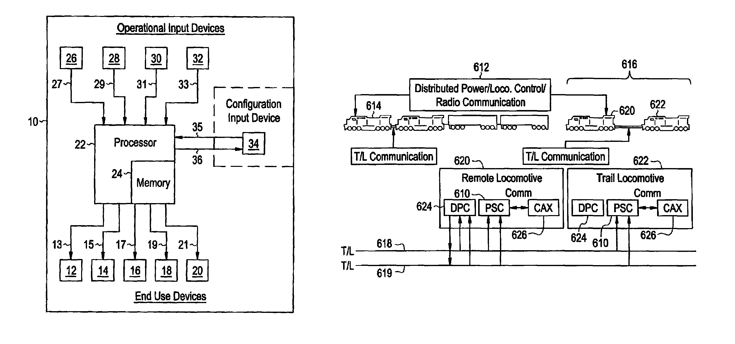
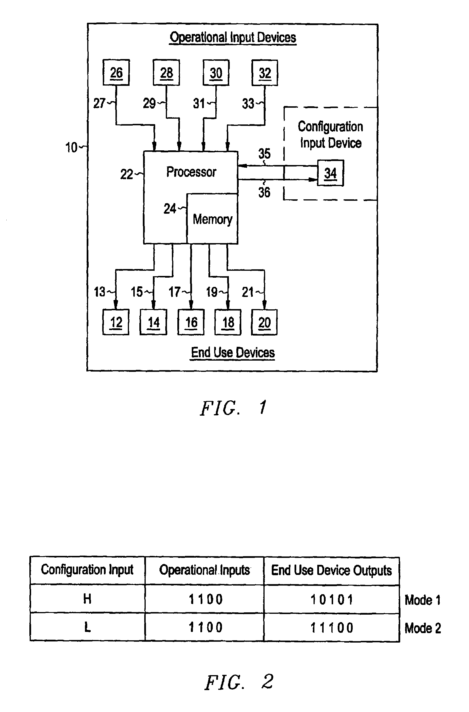
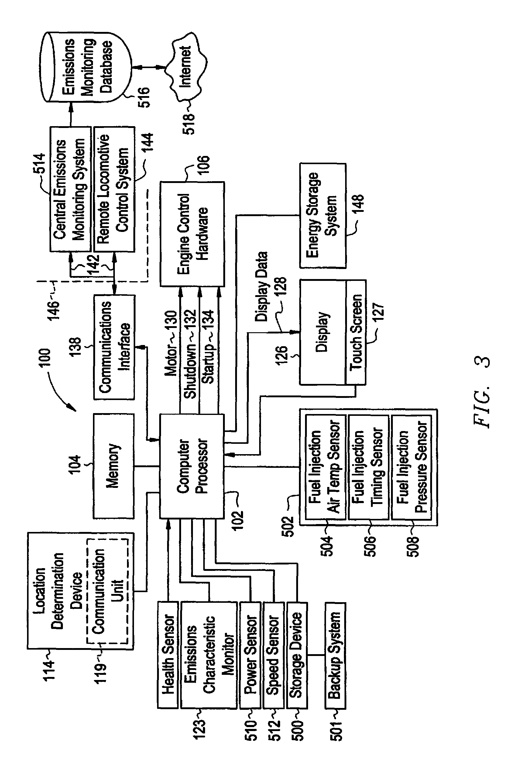
[0026]The applicants of the present invention have discovered that by controlling emissions of diesel powered systems including diesel-fueled power generating unit, such as locomotive engines relative to geographic locations, management of railroad operations such as emissions monitoring and emissions credit trading may be improved over conventional techniques. FIG. 1 is a block diagram of a control system of a diesel-fueled power generating unit, such as a locomotive 10 that can be operated in one of several configurations in order to better match the locomotive 10 to a particular mission. The term configuration is used herein to describe the overall operating profile of a diesel-fueled power generating unit, such as a locomotive, including important operating characteristics and the manner in which the operating systems of the diesel-fueled power generating unit are controlled in response to operational inputs. A diesel-fueled power generating unit's configuration may include perf...


PUM


Abstract

A configurable diesel powered system is provided for controlling engine emissions of a diesel-fueled power generating unit. The diesel-fueled power generating unit includes an engine operating on at least one fuel type. The system includes a plurality of operational input devices coupled with a processor to generate operational input signals to the processor. A plurality of end use devices include fuel tanks for each respective fuel type and are controlled by the processor to control the engine emissions. A configuration input device in communication with the processor generates a respective configuration signal for each particular location along the predetermined course comprising a mission. The processor is responsive to the operational input devices and configuration signals to generate a set of control signals to the fuel tanks to limit the total engine emissions of all fuel types to a respective stored engine emission profile for each configuration signal for each particular location along the predetermined course comprising the mission.

Description

CROSS-REFERENCE TO RELATED APPLICATIONS[0001]The present application is a Continuation-In-Part of U.S. application Ser. No. 11 / 136,769 filed May 25, 2005, now U.S. Pat. No. 7,500,436 which claims priority from U.S. Provisional Application No. 60 / 590,853 filed Jul. 23, 2004, which is a Continuation-In-Part of U.S. application Ser. No. 11 / 008,708 filed Dec. 9, 2004, now U.S. Pat. No. 7,302,895 which also claims priority from U.S. Provisional Application No. 60 / 590,853 filed Jul. 23, 2004.[0002]U.S. application Ser. No. 11 / 008,708 is a Continuation-In-Part of U.S. application Ser. No. 10 / 435,261 filed May 9, 2003, now U.S. Pat. No. 7,231,877 which is a Continuation-In-Part of 10 / 032,714 filed Dec. 26, 2001, now U.S. Pat. No. 6,612,245 issued Sep. 2, 2003, which claims priority from U.S. Provisional No. 60 / 278,975 filed Mar. 27, 2001.[0003]U.S. application Ser. No. 11 / 008,708 filed Dec. 9, 2004 is also a Continuation-In-Part of U.S. application Ser. No. 10 / 354,638 filed Jan. 30, 2003, n...

Claims


Application Information

Patent Timeline
Patent Type & Authority Patents(United States)
IPC IPC(8): B61L11/00B61L3/00
CPCB61L3/006F02D41/0025F02D41/021F02D29/06Y02T10/36F02D2041/1417F02D2200/604F02D2200/701Y02T10/30
Inventor KUMAR, AJITH KUTTANNAIRDAUM, WOLFGANG
Owner GE GLOBAL SOURCING LLC
Why Eureka
Try Eureka