
Replaceable flute inserts for a roller assembly of a debarker apparatus

a technology of roller assembly and debarker, which is applied in the direction of woodworking apparatus, sawing components, tree debarking, etc., can solve the problems of reducing affecting the quality of wood products, so as to reduce the amount of material suitable for making lumber or other wood products, reduce the amount of material suitable for making lumber, and prevent the damage of log ends. , the effect of reducing

Active Publication Date: 2011-02-08
NICHOLSON MFG
View PDF29 Cites 5 Cited by
  • Summary
  • Abstract
  • Description
  • Claims
  • Application Information

AI Technical Summary

Benefits of technology

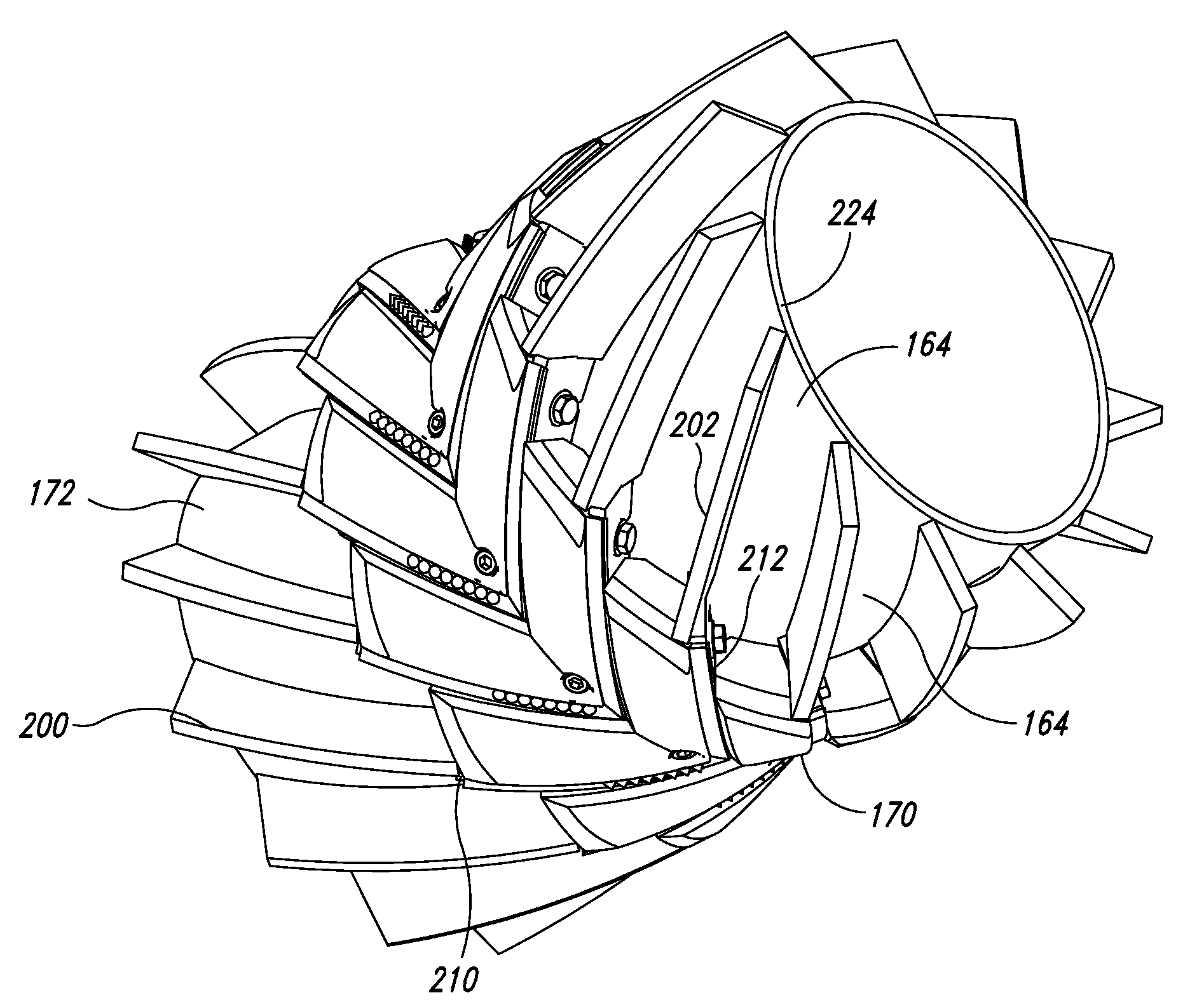
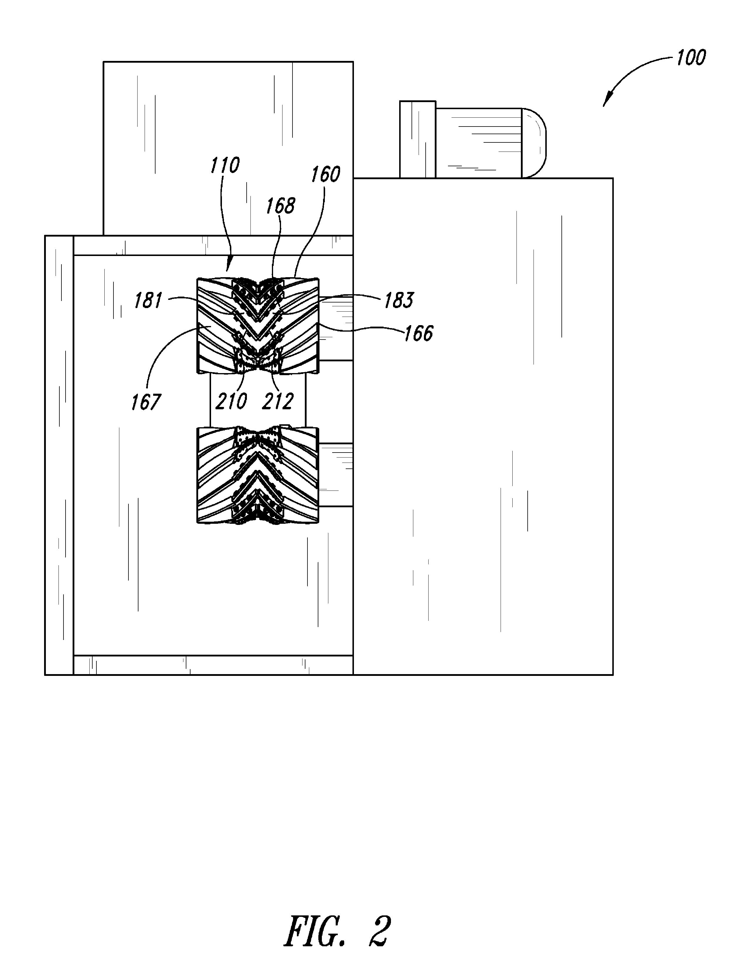
[0007]Some embodiments disclosed herein include the realization that rollers of debarkers can have one or more replaceable flute inserts. The flute inserts can be positioned between flutes fixedly coupled to a roller and can minimize, limit, or substantially prevent damage to log ends. If the flute inserts are not performing properly, the inserts can be quickly replaced. After the inserts have been worn a predetermined amount, for example, the inserts can be quickly replaced resulting in less machine downtime. The inserts can provide suitable high wear surfaces, edges, or other contact regions for engaging logs.
[0008]The inserts can cushion the logs when the logs engage the rollers. In some embodiments, a buffer of the insert receives the log upon initial impact. The buffer then guides the log along the roller. During this process, the buffer can protect the log from the rigid underlying flutes on the roller that would otherwise damage (e.g., chew up) the log. Even though the buffer may be somewhat compressible, the buffer may effectively limit slipping between the roller and the log.

Problems solved by technology

Unfortunately, to accomplish this repair the roll typically must be removed from the debarker apparatus.
The worn flutes are then removed, which is a relatively difficult task because the flutes are often welded to a cylindrical body of the roll.
The flutes (e.g., serrated metal flutes) may also damage logs thereby reducing the amount of material suitable for making lumber or other wood products.
When the logs impact the flutes, for example, the ends of the logs may be damaged.
Thus, traditional fluted rolls may be unsuitable for processing logs.

Method used


Image

  • Replaceable flute inserts for a roller assembly of a debarker apparatus
  • Replaceable flute inserts for a roller assembly of a debarker apparatus
  • Replaceable flute inserts for a roller assembly of a debarker apparatus

Examples


Embodiment Construction

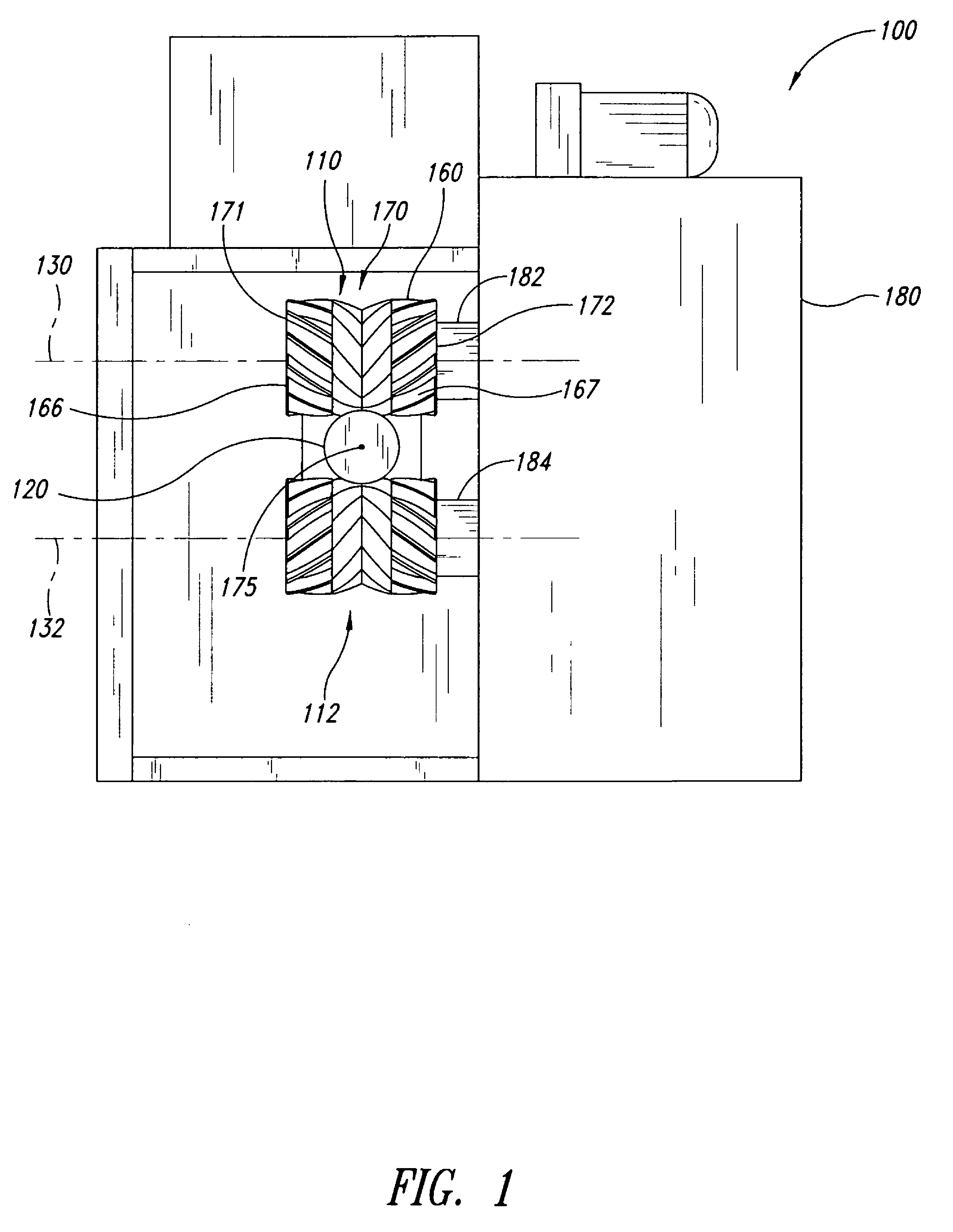
[0036]The present detailed description is generally directed to a debarker apparatus with one or more pairs of roller assemblies, each having a rotatable fluted roller carrying a plurality of replaceable flute inserts. Many specific details of certain exemplary embodiments are set forth in the following description and in FIGS. 1-18 to provide a thorough understanding of such embodiments. One skilled in the art, however, will understand that the disclosed embodiments may be practiced without one or more of the details described in the following description. Additionally, the roller assemblies are discussed in the context of log debarkers because they have particular utility in this context. For example, the roller assemblies are particularly well suited for use at the infeed section, outfeed section, or any other location along a process line of a debarker. If the roller assemblies are positioned at the infeed section, the roller assemblies can be feed roll assemblies that push logs...


PUM


Abstract

Apparatuses, systems, and methods for transporting logs through a debarker are shown and described. The disclosed embodiments of roller assemblies can be used for quickly and conveniently moving logs along a processing line. Some disclosed embodiments include fluted rollers that carry replaceable inserts. The inserts can protect the logs and the rigid flutes of the roller. The insert can be made of a wear resistant material for a prolonged life. A worn insert can be replaced with another insert to ensure proper functioning of the roller assemblies.

Description

BACKGROUND OF THE INVENTION[0001]1. Technical Field[0002]The present disclosure in some embodiments generally relates to a roller assembly, and more specifically to a roller assembly having replaceable flute inserts.[0003]2. Description of the Related Art[0004]Debarker apparatuses often have upper and lower spaced pairs of fluted rolls for moving logs along a processing line. These fluted rolls are commonly at the infeed and / or outfeed sections of the processing line. Flutes on the rolls are often arranged and shaped to grip and propel the logs forward as the rolls rotate. This is often accomplished by having sets of right and left complementing metal flutes meeting at the center of each roll. Each flute has an inner end displaced circumferentially along the roll from an outer end so that, when viewed in elevation, the complementing flutes have a generally “V” shaped configuration.[0005]Central portions of the flutes often provide most of the traction for advancing the log and are c...

Claims


Application Information

Patent Timeline
Patent Type & Authority Patents(United States)
IPC IPC(8): B27L1/00
CPCB27B25/02B27L1/00B27L1/045
Inventor KUBE, BURK R.JEFFREY, DOUGLAS B.CHOLEWCZYNSKI, MAREK S.
Owner NICHOLSON MFG
Learn More