Electro-luminescence display panel and driving method thereof

a technology of e-luminescence display panel and driving method, which is applied in the direction of static indicating device, multi-stage water/sewage treatment, instruments, etc., can solve the problems of deterioration of light-emission efficiency and increase power consumption, and achieve the effect of increasing the light-emitting time of the pixel and reducing power consumption

Active Publication Date: 2011-02-08
LG DISPLAY CO LTD
View PDF2 Cites 3 Cited by
  • Summary
  • Abstract
  • Description
  • Claims
  • Application Information

AI Technical Summary

Benefits of technology

[0015]Accordingly, it is an object of the present invention to provide an electro-luminescence display panel and a driving method thereof that are adaptive for increasing a light-emitting time of a pixel as well as reducing power consumption.

Problems solved by technology

As a result, as voltage levels of the data signals Vdata1 to Vdata3 go higher, that is, as swing widths thereof go larger, the rising times t1 to t3 thereof are more increased to reduce a light-emitting period of the EL cells to that extent, thereby causing a deterioration of light-emission efficiency.
Furthermore, power consumption is increased due to the large swing widths of the data signals Vdata1 to Vdata3.

Method used


Image

  • Electro-luminescence display panel and driving method thereof
  • Electro-luminescence display panel and driving method thereof
  • Electro-luminescence display panel and driving method thereof

Examples


Embodiment Construction

[0026]Reference will now be made in detail to the preferred embodiments of the present invention, examples of which are illustrated in the accompanying drawings.

[0027]Hereinafter, the preferred embodiments of the present invention will be described in detail with reference to FIGS. 4 and 5.

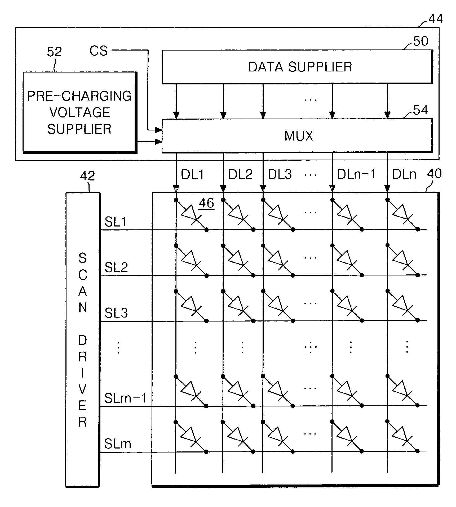
[0028]FIG. 4 is a schematic block circuit diagram equivalently representing a configuration of a passive matrix type electro-luminescence (EL) display panel according to an embodiment of the present invention.

[0029]Referring to FIG. 4, the EL display panel includes a pixel matrix 40 having EL cells 46 provided for each intersection area between scan lines SL1 to SLm and data lines DL1 to DLn, a scan driver 42 for driving the scan lines SL1 to SLm, and a data driver 44 for driving the data lines DL1 to DLn.

[0030]Each of EL cells 46 can be expressed as a diode provided at the intersection area between the data line DL and the scan line SL. If a negative scanning pulse is applied to the scan line as ...


PUM


Abstract

An electro-luminescence display panel and a driving method thereof for increasing a light-emitting time of a pixel as well as reducing power consumption are disclosed. In the electro-luminescence display panel, a pixel matrix has a plurality of electro-luminescence cells connected between scan lines and data lines. A scan driver drives the scan line. A data driver pre-charges the data lines into a middle voltage of data signals and then supplies corresponding data signals.

Description

[0001]This application claims the benefit of Korean Patent Application No. P2004-11589 filed in Korea on Feb. 20, 2004, which is hereby incorporated by reference.BACKGROUND OF THE INVENTION[0002]1. Field of the Invention[0003]This invention relates to an electro-luminescence display (ELD), and more particularly to an electro-luminescence display panel and a driving method thereof that are adaptive for increasing a light-emitting time of a pixel as well as reducing power consumption.[0004]2. Description of the Related Art[0005]Recently, there have been highlighted various flat panel display devices reduced in weight and bulk that is capable of eliminating disadvantages of a cathode ray tube (CRT). Such flat panel display devices include a liquid crystal display (LCD), a field emission display (FED), a plasma display panel (PDP) and an electro-luminescence (EL) display panel, etc.[0006]The EL display panel of these display devices is a self-luminous device capable of light-emitting a ...

Claims


Application Information

Patent Timeline
Patent Type & Authority Patents(United States)
IPC IPC(8): G09G3/30G09G3/32
CPCG09G3/3216G09G2310/0248C02F1/283C02F1/52C02F7/00C02F9/00
Inventor LEE, JAE DOKIM, KI HEONKIM, HAK SU
Owner LG DISPLAY CO LTD
Why Eureka
Try Eureka