LED driver circuit

a driver circuit and led technology, applied in the direction of electroluminescent light sources, electric lighting sources, semiconductor lamp usage, etc., can solve the problems of low quality and high circuit cost of circuit b>100/b>, and achieve the effect of increasing the light emission time of leds

Inactive Publication Date: 2013-10-17
MEMCHIP TECH
View PDF2 Cites 2 Cited by
  • Summary
  • Abstract
  • Description
  • Claims
  • Application Information

AI Technical Summary

Benefits of technology

[0008]In view of the fact that a conventional LED driver circuit requires a large-capacity capacitor in order to enable sustained emission of light from the LED(s) to be driven, the inventor of the present invention put years of practical experience into extensive research and experiment and finally succeeded in developing an LED driver circuit in which a capacitor is controlled by a switch and will not be discharged to an LED unless the input voltage is relatively low. The present invention provides a circuit arrangement in which a small-capacity, low-cost capacitor will suffice to effectively increase the light emission time of an LED.
[0009]It is an object of the present invention to provide an LED driver circuit which includes a controller, a switch device, a capacitor, and at least one LED. The capacitor and the at least one LED are respectively connected in parallel to a power source through the switch device. The controller has an input end connected to a line between the switch device and the power source and is configured for detecting an input voltage of the power source. When determining that the input voltage is higher than the forward bias voltage of the at least one LED, the controller generates a first control signal and sends the first control signal to the switch device through the output end of the controller, causing the switch device to make both the connection between the power source and the capacitor and the connection between the power source and the at least one LED, so as for the input voltage to not only drive the at least one LED to emit light, but also charge the capacitor simultaneously. Conversely, when determining that the input voltage is lower than the forward bias voltage of the at least one LED, the controller generates a second control signal and sends the second control signal to the switch device through the output end of the controller, causing the switch device to make only the connection between the capacitor and the at least one LED, so as for a discharge voltage of the capacitor to drive the at least one LED to emit light. Thus, the driver circuit only needs a small-capacity, low-cost capacitor in order to increase the light emission time of the at least one LED effectively, and the circuit cost of the driver circuit can be lowered.

Problems solved by technology

Nevertheless, as a large-capacity capacitor 15 generally can only be implemented by an electrolytic capacitor, which is both costly and prone to damage, the resultant LED driver circuit 100 will have a high circuit cost and less-than-satisfactory quality.

Method used


Image

  • LED driver circuit
  • LED driver circuit
  • LED driver circuit

Examples


Embodiment Construction

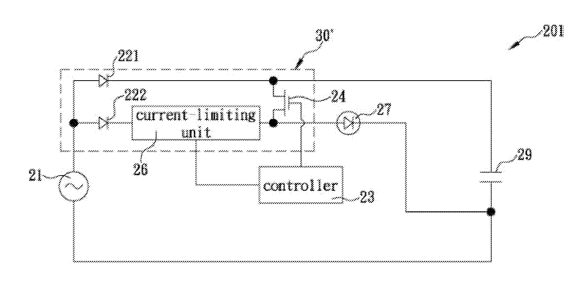
[0021]Please refer to FIG. 4 for a schematic circuit diagram of the LED driver circuit according to a preferred embodiment of the present invention. As shown in the drawing, the LED driver circuit 200 in this embodiment includes a power source 21, a controller 23, a switch device 30, at least one LED 27, and a capacitor 29.

[0022]The power source 21 can provide a DC input voltage. The capacitor 29 and the LED 27 are respectively connected in parallel to the power source 21 via the switch device 30. The input end of the controller 23 is connected to a line between the switch device 30 and the power source 21 in order for the controller 23 to detect an input voltage provided by the power source 21. Upon determining that the input voltage is higher than the forward bias voltage of the LED 27, the controller 23 generates a first control signal and sends the first control signal to the switch device 30 via the output end of the controller 23. Thus, the switch device 30 is driven to make t...


PUM


Abstract

The present invention is to provide an LED driver circuit which includes a capacitor and at least one LED respectively connected in parallel to a power source through a switch device, and a controller having an input end connected to a line between the switch device and the power source and being configured for detecting an input voltage applied to the LED. When the controller detected that the input voltage is unable to drive the LED to emit light, the controller activates the switch device to make only the connection between the capacitor and the at least one LED, such that the capacitor discharges a voltage stored therein to the at least one LED to continuously emit light. Since the driver circuit only needs a small-capacity, low-cost capacitor for increasing the light emission time of the at least one LED, the cost of the driver circuit can be lowered effectively.

Description

FIELD OF THE INVENTION[0001]The present invention relates to an LED driver circuit, more particularly to an LED driver circuit having a controller to detect a voltage or current applied to the LED and capable of enabling a capacitor to discharge a voltage stored therein to the LED for continuously emitting light when the controller detected that the voltage or current can't drive the LED to emit light.BACKGROUND OF THE INVENTION[0002]Light-emitting diodes (LEDs) are light-emitting elements made of semiconductor materials whose properties enable conversion from electric energy into light energy. LEDs have been massively used in lighting- and display-related applications due to their small physical volumes, long lifetimes, low driving voltages, short response times, and ready adaptability to various products in our daily lives.[0003]FIG. 1 schematically shows the circuit structure of a conventional simple LED driver circuit 100, which includes a power source 11 and at least one LED 13...

Claims


Application Information

Patent Timeline
Patent Type & Authority Applications(United States)
IPC IPC(8): H05B33/08H05B44/00
CPCH05B33/0815H05B45/395Y02B20/30H05B45/3725
Inventor LIANG, WEI-CHENHOU, FU-HSING
Owner MEMCHIP TECH
Why Eureka
Try Eureka