
Systems and methods for robotic gutter cleaning along an axis of rotation

a technology of robotic gutter cleaning and axis rotation, which is applied in the direction of carpet cleaners, cleaning machines, lighting and heating apparatus, etc., can solve the problems of difficult and dangerous cleaning of gutter debris, and achieve the effect of reducing the torque of the impeller drive facility

Inactive Publication Date: 2011-02-15
IROBOT CORP
View PDF97 Cites 42 Cited by
  • Summary
  • Abstract
  • Description
  • Claims
  • Application Information

AI Technical Summary

Benefits of technology

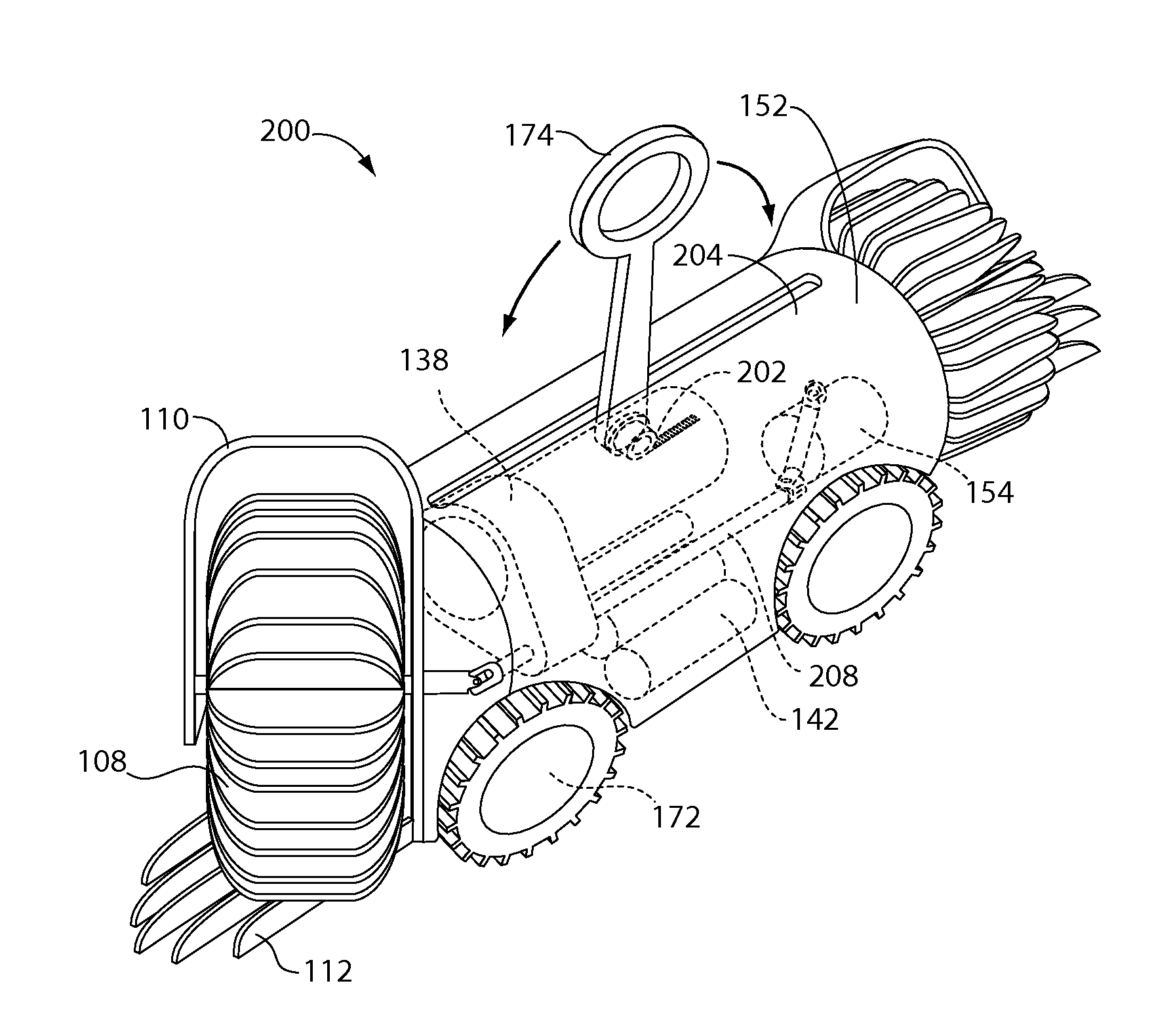
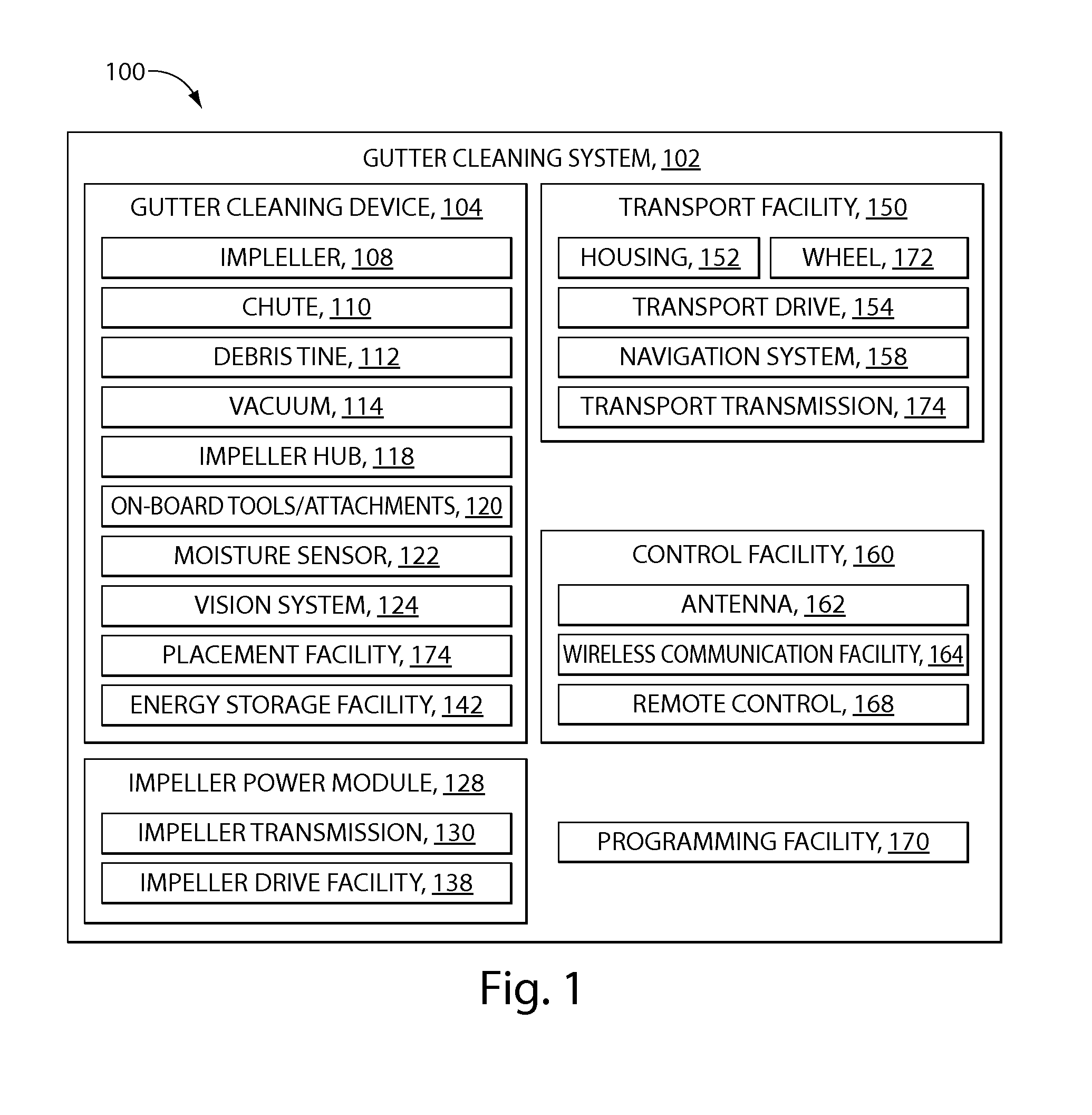
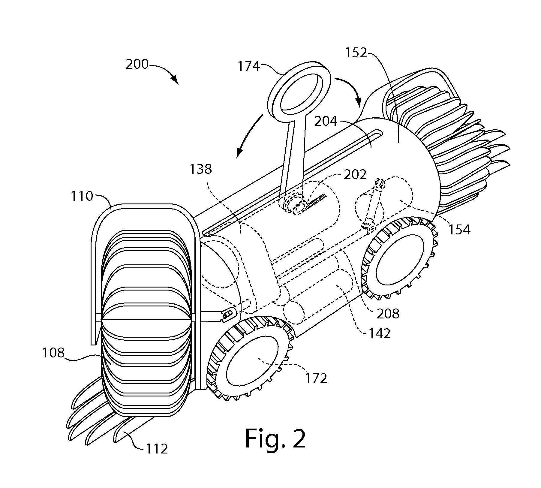
The patent describes a gutter cleaning system that includes a device for cleaning gutters. The device includes a housing that fits into the gutter and an impeller that is driven by a motor. The device can be placed in the gutter using a pole that attaches to the device. The impeller is designed to remove debris from the gutter. The device can also have a navigation system to help it move around the gutter. The system also includes an energy storage facility to power the device. The device can be controlled remotely or autonomously. The system also includes a placement pole that can be extended to help the device fit into the gutter. The device can be made from materials like metal, plastic, or molded elastomer. The system can also have a vacuum attachment to remove debris from the gutter. The device can be programmed using a wireless or direct connection to a programming interface. Overall, the system provides a convenient and effective way to clean gutters.

Problems solved by technology

Cleaning debris from a gutter may be difficult and dangerous, especially when an individual uses a ladder to reach the gutter and leans laterally to reach portions of the gutter for cleaning.

Method used


Image

  • Systems and methods for robotic gutter cleaning along an axis of rotation
  • Systems and methods for robotic gutter cleaning along an axis of rotation
  • Systems and methods for robotic gutter cleaning along an axis of rotation

Examples


Embodiment Construction

[0045]Throughout this disclosure the phrase“such as” means “such as and without limitation.” Throughout this disclosure the phrase “for example” means “for example and without limitation.” Throughout this disclosure the phrase “in an example” means “in an example and without limitation.” Throughout this disclosure the phrase “in another example” means “in another example and without limitation.” Generally, any and all examples may be provided for the purpose of illustration and not limitation.

[0046]The present invention may comprise a robotic drainage channel (gutter) cleaning system. The cleaning system may comprise a remotely operated device for cleaning drainage channels, or “gutters” and methods thereof. Gutter cleaning may involve removing debris, such as leaves, bark, twigs, nut shells, nuts, airborne matter, bird's nests, ice, water, foreign objects, and any other matter that may accumulate in a gutter. The gutter cleaning system may comprise an impeller, a chute at each end ...


PUM

PropertyMeasurementUnit
diameteraaaaaaaaaa
speedaaaaaaaaaa
flexibleaaaaaaaaaa

Abstract

In embodiments of the present invention, a gutter-cleaning device comprises a housing containing an impeller drive facility, the housing configured to fit into a gutter, an impeller, disposed at an end of the housing and driven by the impeller drive facility, and a transport facility for transporting the housing along the gutter. The impeller may have an axis of rotation, the axis of rotation oriented toward an inside corner of the gutter and the impeller drive facility may be adapted to rotate the impeller on the axis of rotation. Transport of the housing through the gutter may cause the impeller to travel along an axis of motion, the axis of motion differing from the axis of rotation.

Description

CROSS-REFERENCE TO RELATED APPLICATIONS[0001]This application claims the benefit of the following provisional applications, each of which is hereby incorporated by reference in its entirety:[0002]U.S. Provisional Application 60 / 984,836, filed Nov. 2, 2007.[0003]This application is a continuation-in-part of the following U.S. patent applications, each of which is incorporated by reference in its entirety: U.S. application Ser. No. 11 / 834,908, filed Aug. 7, 2007 which claims the benefit of U.S. Provisional Application No. 60 / 838,100, filed on Aug. 15, 2006.BACKGROUND[0004]1. Field[0005]The present invention generally relates to systems and methods for robotic gutter cleaning.[0006]2. Description of the Related Art[0007]Cleaning debris from a gutter may be difficult and dangerous, especially when an individual uses a ladder to reach the gutter and leans laterally to reach portions of the gutter for cleaning.SUMMARY[0008]Provided herein may be methods and systems for gutter cleaning and...

Claims


Application Information

Patent Timeline
Patent Type & Authority Patents(United States)
IPC IPC(8): A46B13/02
CPCB08B9/00E04D13/0765B08B9/051B08B9/049
Inventor DAYTON, DOUGLAS C.PARK, SUNGABELE, KARL EATONROBINSON, JASON
Owner IROBOT CORP
Learn More