Foldable knife having switch element

a switch element and folding knife technology, applied in the field of folding knives, can solve the problems of user's use of both hands to rotate the blade out of the handle, serious risk to the life of fisherman, and the user cannot speedily use the traditional foldable knife to deal with the particular or emergent condition, etc., to enhance the operation and the effect of enhancing the operational convenience and safety of the foldable kni

Inactive Publication Date: 2011-02-15
KAO CHIH CHEN
View PDF13 Cites 21 Cited by
  • Summary
  • Abstract
  • Description
  • Claims
  • Application Information

AI Technical Summary

Benefits of technology

[0007]A primary object of the present invention is to provide a foldable knife, which foldable knife comprises a handle, a blade, a spring, a blocking portion, and a poking element, wherein the handle has a receiving space, and the blade has an end pivotally connected to an end of the handle by a pivot. The pivot is mounted with the spring, which has two ends connected to the handle and the blade, respectively, so that the spring can bias the blade with a torque to rotate the blade out of the handle. The blocking element is provided at an inner portion of the handle adjacent to the pivot. When the blade has sprung completely out of the handle, the blocking element is engaged with the end of the blade, so as to prevent the blade from being rotated and received in the receiving space of the handle. When the blocking element is forced and moved away from an engaged position where the blocking element is engaged with the blade, the blade is released for being rotated, so that the blade can be completely received in the handle. The blocking element is formed with a positioning portion, while the blade is formed with an engaging portion. When the blade is completely received in the handle, the engaging portion is engaged with the positioning portion, so that the blade can be stably received and positioned in the handle.
[0008]A secondary object of the present invention is to provide a foldable knife having a poking element, so as to enhance the operational convenience and safety of the foldable knife. The poking element is pivotally connected to an inner portion of the handle, and has a first end extended out of the handle for being pushed by a user. When the blade is completely received in the handle, a second end of the poking element bears against the blade. Thus, when the user pushes the first end of the poking element, the positioning portion can be disengaged from the engaging portion. Meanwhile, the torque of the spring drives the blade to spring out of the handle. Therefore, while holding the handle stably in one hand, a user can use a finger of the same hand to push the poking element, so that the blade will spring automatically out of the handle without the user having to substantially adjust a holding area on the handle. As a result, the operational convenience and safety of the foldable knife is greatly enhanced, allowing the user to use the foldable knife speedily or smoothly to deal with a particular or emergent condition.

Problems solved by technology

However, a major disadvantage of the traditional foldable knife is that the user must use both hands to rotate the blade out of the handle.
If a particular or emergent condition happens and the user only has one free hand to use, the user cannot speedily use the traditional foldable knife to deal with the particular or emergent condition.
For example, when a fisherman is diving and has one hand entangled by a fishnet, the fisherman cannot speedily use the traditional foldable knife to cut the fishnet, resulting in a serious risk to the fisherman's life.
However, because the blade 11 of the traditional foldable knife must be formed with the protrusion 112 having a considerable height and size, the structure of the protrusion 112 may lower the design aesthetics of the traditional foldable knife.
However, it is inconvenient for the user to execute the foregoing operation, and the traditional foldable knife may drop from the hand of the user if the user cannot stably hold the handle 10 with only one hand.
If a particular or emergent condition happens and the user only has one free hand to use, the user still cannot use the traditional foldable knife speedily or smoothly to deal with the particular or emergent condition.

Method used


Image

  • Foldable knife having switch element
  • Foldable knife having switch element
  • Foldable knife having switch element

Examples


Embodiment Construction

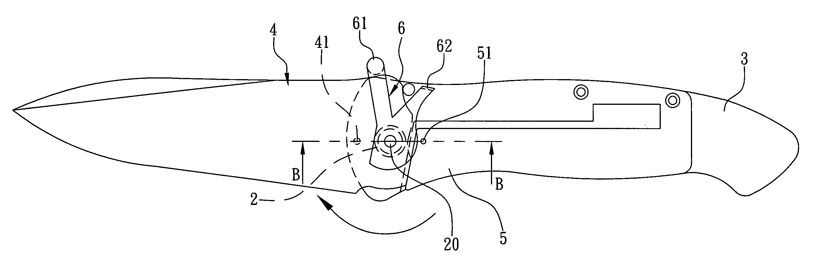
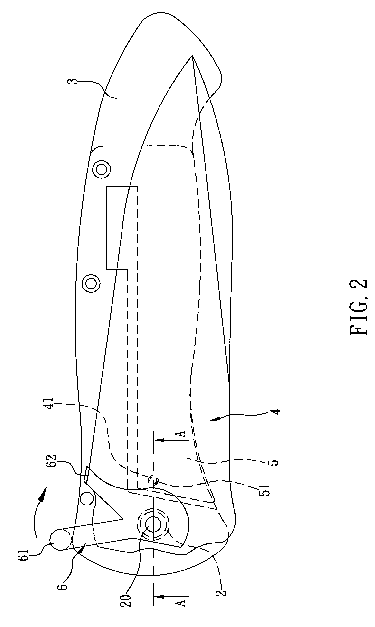
[0020]Referring now to FIGS. 2 and 3, where a foldable knife having a poking element according to a first preferred embodiment of the present invention is illustrated. As shown, the foldable knife comprises a torsion spring 2, a handle 3, a blade 4, a blocking element 5, and a poking element 6, wherein the handle 3 is a hollow structure, and the blade 4 has an end pivotally connected to an end of the handle 3 by a pivot 20. Thus, the blade 4 can be rotated out of the handle 3 in relation to a central axis defined by the pivot 20 so that the blade 4 can be used to cut an article. Or alternatively, the blade 4 can be rotated into the handle 3 and received therein for reducing the volume of the foldable knife for easy carriage and preventing the blade 4 from endangering a user or some other articles. The pivot 20 is mounted with the torsion spring 2, which has a first end connected to a portion of the handle 3 adjacent to the pivot 20 and a second end connected to a portion of the blad...


PUM


Abstract

A foldable knife comprises a blade having an end pivotally connected to an end of a handle, and a spring having two ends connected to the handle and blade respectively, so that the spring can apply a torque to the blade to rotate the blade out of the handle. A blocking element is provided at an inner portion of the handle. A switch element pivotally connected to the inner portion of the handle has a first end extended out of the handle. When the blade is completely received in the handle, a second end of the switch element bears against the blade. When the user pushes the first end of the switch element, a positioning portion formed on the blocking element is disengaged from an engaging portion formed on the blade, so that the torque of the spring drives the blade to spring out of the handle.

Description

FIELD OF THE INVENTION[0001]The present invention relates to a foldable knife, and more particularly to a foldable knife having a switch element.BACKGROUND OF THE INVENTION[0002]Presently, a traditional foldable knife generally comprises a handle and a blade, wherein the blade has an end pivotally connected to an end of the handle. Thus, the blade can be rotated in relation to a pivot portion thereof until the blade is rotated out of the handle for use. Alternatively, the blade also can be rotated into the handle and received therein. When a user wants to use the traditional foldable knife, the user must hold the handle in one hand and draw the blade with the other hand, so as to rotate the blade out of the handle. However, a major disadvantage of the traditional foldable knife is that the user must use both hands to rotate the blade out of the handle. If a particular or emergent condition happens and the user only has one free hand to use, the user cannot speedily use the tradition...

Claims


Application Information

Patent Timeline
Patent Type & Authority Patents(United States)
IPC IPC(8): B26B1/02
CPCB26B1/044B26B1/042B26B1/046
Inventor KAO, CHIH-CHEN
Owner KAO CHIH CHEN
Why Eureka
Try Eureka