Height control valve for vehicle leveling system

a technology of height control valve and vehicle suspension, which is applied in the direction of valve operating means/release devices, cycle equipment, instruments, etc., can solve the problems of affecting the handling of trailers, affecting the stability of trailers, and reducing the distance between the frame and the axle, so as to achieve accurate inflating and deflating of vehicle suspension elements, improve load stability, and simple and efficient

Active Publication Date: 2011-02-15
LINK MFG
View PDF33 Cites 22 Cited by
  • Summary
  • Abstract
  • Description
  • Claims
  • Application Information

AI Technical Summary

Benefits of technology

[0006]The present invention provides a height control valve that precisely and accurately supplies and exhausts the appropriate amount of fluid to one or more suspension elements of a vehicle.
[0010]In yet another embodiment, the control unit can include a controller which is in communication with the sensor. The controller can determine when the sensor senses movement of the actuator, and thus a change in the distance between the vehicle members. As a result, the controller can control the valve assembly to reconfigure it to the supply, closed or exhaust positions as required.
[0013]The present invention provides a simple and efficient height control valve that precisely and accurately inflates and deflates vehicle suspension elements. The height control valve can consistently actuate a valve assembly, which in turn, modifies the attitude, pitch, roll, or tilt of the vehicle. In turn, the vehicle can obtain significantly improved load stability, as well as surprising and unexpected results of improved fuel economy up to 3% over conventional mechanical ride height control valves. In addition, the present invention is usually unaffected by the physical wear. For example, where the control unit includes a non-contact sensor for determining actuator movement, there are no sensor parts prone to wearing out. Further, even where the linkage between the servo and valve assembly wears, with the controller adapted to sense when the servo engages the valve assembly, such wear has little—if any—adverse effect on the precise positioning of the plunger and thus operation of the valve. In turn, even as parts of the height control valve wear, the performance of the valve remains relatively unaffected.

Problems solved by technology

For example, with semi-trailers, heavy loads can cause the suspension to sag, thereby decreasing the distance between the frame and the axle.
Further, if the load is not evenly distributed throughout the trailer, the load may also alter the attitude of the trailer, for example, the fore-aft tilt and / or side-to-side tilt.
These conditions can adversely affect the handling of the trailer, and can even result in damage to the suspension, frame and axle.
When the distance between the axle and frame falls below the desired position, the height control valve automatically causes inflation of the suspension, and when the distance between the axle and the frame is too great, the height control valve automatically causes the suspension to exhaust.
For example, the mechanical connection between the control arm and the valve assembly of a mechanical height control valve wears over time.
With this wear, the sensitivity and exact positioning of the valve, and thus the precise inflation or deflation of the suspension, is compromised.
In addition, the tolerances between the control arm and the valve assembly can deteriorate with such wear, or simply from improper adjustment.
In turn, the mechanical ride height control valve may not timely inflate or deflate enough air from the suspension.
Alternatively, the mechanical connection between the actuator and the valve assembly may become so worn that it cannot properly control the valve assembly, and therefore the height leveling ability of the height control valve becomes significantly diminished.
As a result, the vehicle is not properly leveled, and this condition can have adverse affects on vehicle stability and fuel consumption.

Method used


Image

  • Height control valve for vehicle leveling system
  • Height control valve for vehicle leveling system
  • Height control valve for vehicle leveling system

Examples


Embodiment Construction

I. Overview

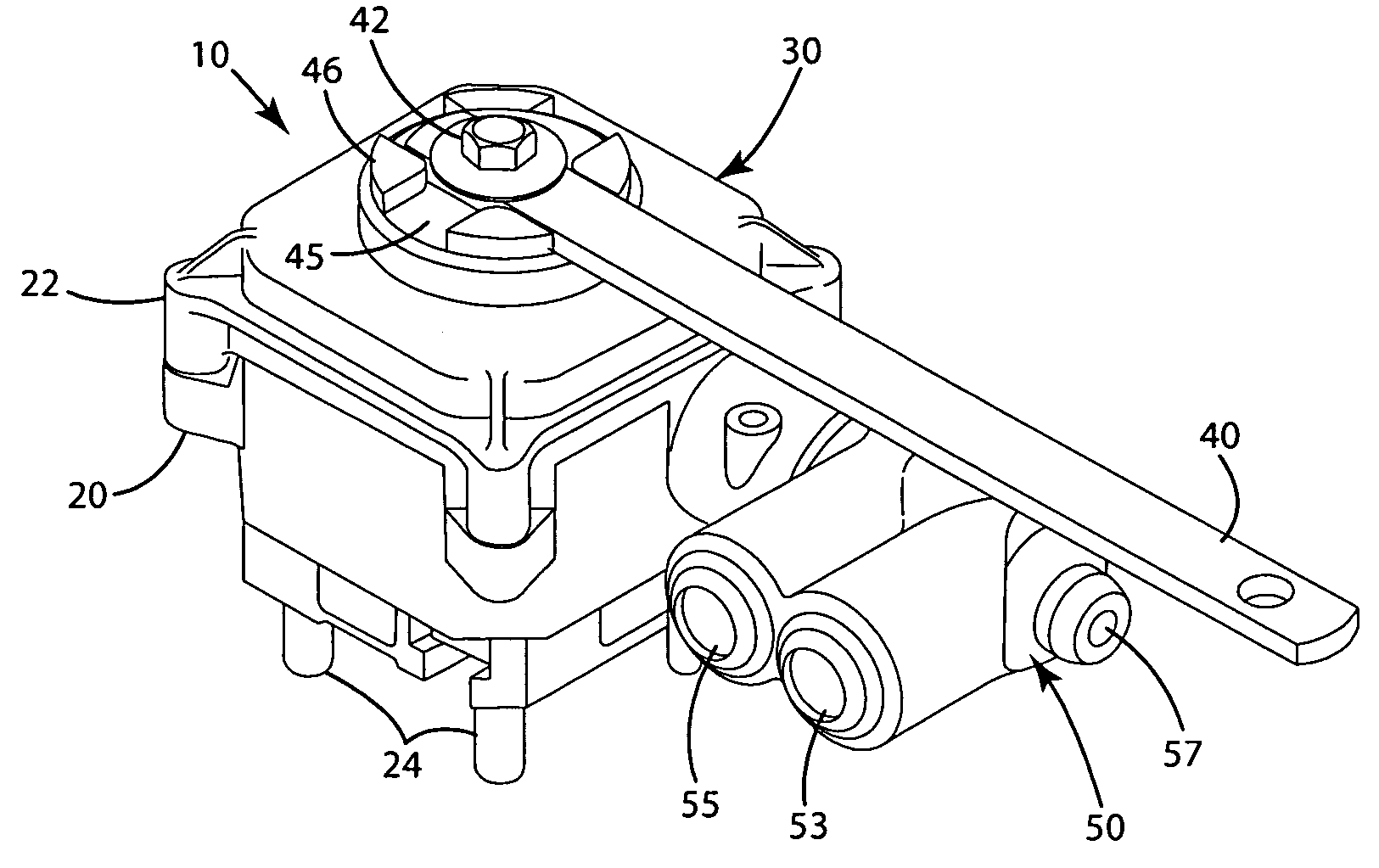
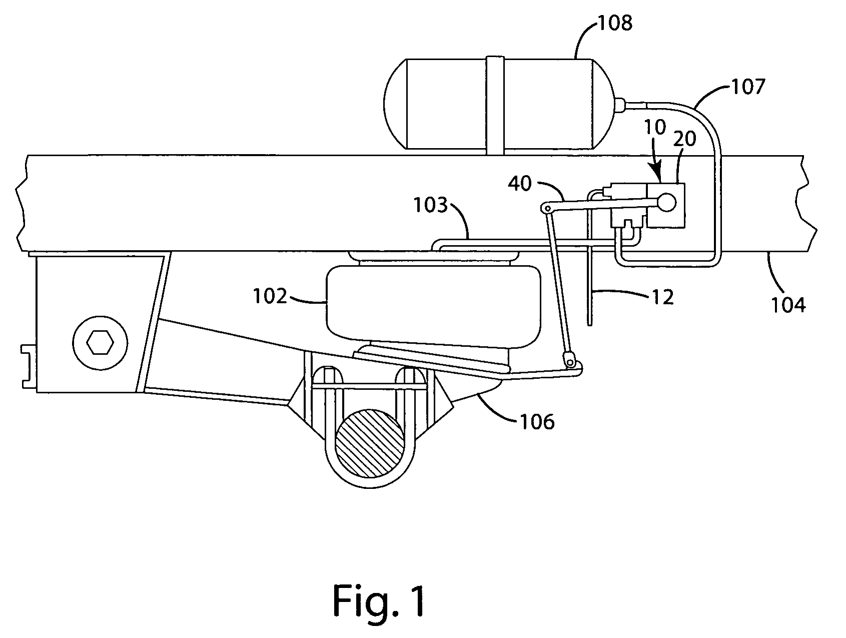
[0028]A ride height control valve constructed in accordance with an embodiment of the invention is illustrated in FIGS. 1-9 and generally designated 10. Generally, the height control valve 10 is described in connection with a leveling system where the valve functions to control the flow of air into and out of suspension elements 102, for example, an air spring associated with a vehicle, such as, a semi-tractor, a semi-trailer, a truck, an automobile or a tractor. The height control valve 10 is also well suited for use in a variety of other height control systems, such as a truck cab system that levels the truck cab with respect to a truck frame, controls the truck cab ride height, or controls the truck cab spacing.

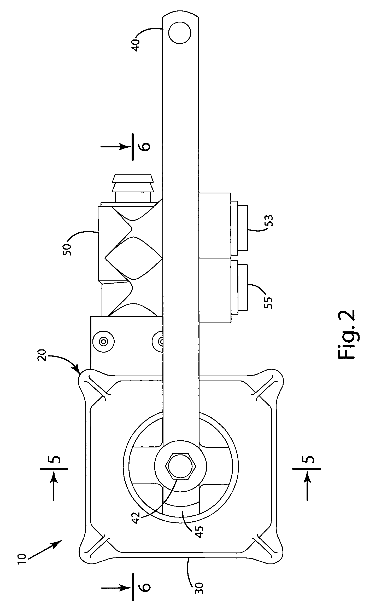
[0029]The height control valve 10 generally includes a housing 20, a control unit 30 and a valve assembly 50, which act in concert to supply or exhaust fluids from the suspension elements or which remain closed so that the suspension elements maintain a static c...


PUM


Abstract

A height control valve for a suspension leveling system includes a control unit and a valve assembly. The control unit can include a servo powered by a servo current, the servo being coupled to the valve assembly with a linkage. The control unit also can include a controller in communication with the servo and adapted to sense a change in the servo current when the linkage fully engages the valve assembly to reconfigure the valve assembly to a desired supply, exhaust and / or closed position. Based on the change in servo current, the controller can determine a selected distance to move or reconfigure the valve assembly, with distance being independent of any wear or tolerance in the linkage or elsewhere. The control unit can also include an actuator, the movement of which is sensed by a non-contact sensor that is in communication with the controller.

Description

BACKGROUND OF THE INVENTION[0001]The present invention relates to a leveling system for a vehicle, and more particularly to a height control valve for use with such a leveling system.[0002]Many vehicles include leveling systems that automatically adjust the suspension of the vehicle to compensate for various loads. These systems are installed in various vehicles, ranging from passenger cars to semi-trucks and semi-trailers. A conventional leveling system includes pneumatic suspension elements, such as shocks or air springs, that can be inflated or deflated to control the height of the frame with respect to the axle. For example, with semi-trailers, heavy loads can cause the suspension to sag, thereby decreasing the distance between the frame and the axle. Further, if the load is not evenly distributed throughout the trailer, the load may also alter the attitude of the trailer, for example, the fore-aft tilt and / or side-to-side tilt. These conditions can adversely affect the handling...

Claims


Application Information

Patent Timeline
Patent Type & Authority Patents(United States)
IPC IPC(8): B60G17/04
CPCB60G17/0155B60G17/0525F16K11/07F16K31/047B60G2200/312B60G2202/1522B60G2500/30
Inventor TRUDEAU, CURTIS A.PIERCE, MARK W.
Owner LINK MFG
Why Eureka
Try Eureka