Lever engaging type connector

a type connector, lever-engagement technology, applied in the direction of coupling device connection, coupling/disconnecting parts, electrical apparatus, etc., can solve the problems of rotating operation becoming further heavy, affecting the operation of the coupling, etc., to prevent the occurrence of backlash or unstable electrical connection between the terminals, and the terminals being reliably and smoothly engaged

Active Publication Date: 2011-02-15
YAZAKI CORP
View PDF7 Cites 0 Cited by
  • Summary
  • Abstract
  • Description
  • Claims
  • Application Information

AI Technical Summary

Benefits of technology

[0015]The invention has been made in view of the above described circumstances, and it is an object of the invention to provide a lever engaging type connector, in which in case of connecting a male connector to a female connector by operating a lever, an inclination of the male connector is corrected, by moving a pivot of the lever little by little so that the inclined male connector may be made parallel to the female connector, whereby the male and female connectors can be opposed to each other in parallel, at least at initiation of connection between female terminals and male terminals of the respective connectors, so that engagement of the male terminals with the female terminals can be coaxially and smoothly performed, without applying excessive stress to the terminals, and further, occurrence of a backlash between the male connector and the lever can be prevented, after the connection (engagement) between the female connector and the male connector has been completed.
[0020]According to the structure as described above in (1), in case where the lever is not operated to rotate, and the male connector having the boss part rotatably held in the hole of the lever is inserted into the female connector, while the pivot projection of the lever is guided into the pivot projection guiding groove in the female connector, the male connector will float up with respect to the female connector. On the other hand, the pivot projection of the lever is positioned in the pivot projection receiving groove, after the unrotatable state of the lever by the temporarily locking means has been released, and therefore, when the lever is operated to rotate around the pivot projection as the pivot, the thick wall part presses the operation part side of the male connector. As the results, an inclination of the lever is changed little by little around the pivot projection, and an inclination of the male connector is corrected gradually in the rotating process of the lever or before and after completion of the rotation, whereby the lever allows the male connector to be opposed to the female connector substantially in parallel. In this manner, the terminals of the respective connectors are smoothly and coaxially engaged with each other in the rotating process of the lever or before and after the completion of the rotation, and the optimal engaged state can be obtained without exerting an excessive stress on each other. Moreover, the thick wall part depresses occurrence of a backlash due to clearances of various kinds between the lever and the male connector, including a clearance required for the pivot projection moving in the pivot projection receiving groove, and hence, smooth engagement between the terminals by the correction of the inclination of the male connector can be achieved.
[0022]According to the structure as described above in (3), the terminals of the respective connectors have been already coaxially positioned, before the terminals are engaged with each other, and hence, these terminals can be reliably and smoothly engaged with each other.
[0023]According to the invention, in case of coupling the male connector to the female connector by operating the lever, the male connector can be opposed to the female connector in parallel with each other, at least at the initiation of the engagement between the female terminals and the male terminals of the respective connectors, and hence, the engagement between the female terminals and the male terminals can be performed smoothly and coaxially, without applying excessive stress to the terminals. Moreover, after the male connector and the female connector have been coupled to each other, the respective terminals are tightly and coaxially engaged with each other, and occurrence of a backlash or unstable electrical connection between the terminals can be prevented beforehand.

Problems solved by technology

Consequently, smooth engagement between the female terminals and the male terminals is not performed, and the rotating operation of the lever 122 becomes heavy, incurring abrasion of the terminals.
In short, there has been such inconvenience that a depth of contact between a pair of the terminals is different between the operating part side and the pivot projection side, and hence, the rotating operation becomes further heavy.

Method used


Image

  • Lever engaging type connector
  • Lever engaging type connector
  • Lever engaging type connector

Examples


Embodiment Construction

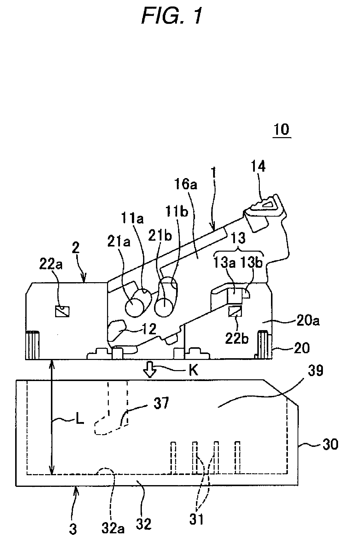
[0061]Now, a lever engaging type connector 10 in an embodiment according to the invention will be described referring to FIGS. 1 to 17.

[0062]The lever engaging type connector 10 in the embodiment as shown in FIG. 1 includes a male type connector (hereinafter referred to as “the male connector”) 2, a lever 1 which is rotatably provided on a connector housing 20 of this male connector 2, and a female type connector (hereinafter referred to as “the female connector”) 3 which has a connector housing 30 having an engaging space 39 into which the male connector 2 is inserted. By rotating the lever 1, the male connector 2 is pushed deep into the engaging space 39 along an engaging direction K thereby to be engaged with the female connector 3.

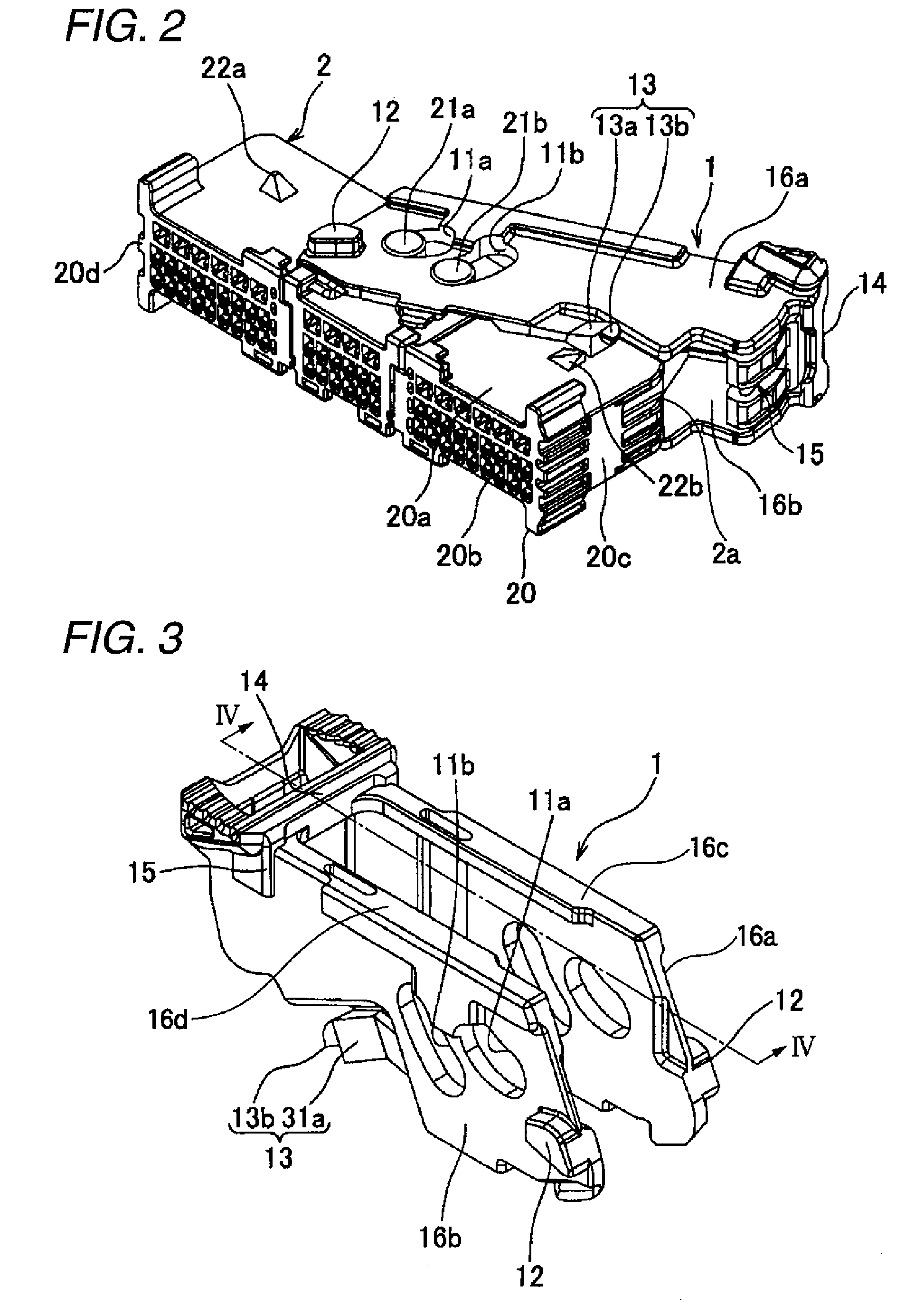
[0063]As shown in FIGS. 1 and 2, the male connector 2 includes the connector housing 20 formed of insulating synthetic resin in a rectangular shape, and terminals (female terminals) 29 which are contained in this connector housing 20 (See FIG. 14B). Th...


PUM


Abstract

To enable a male connector and a female connector to be opposed to each other in parallel, at least when female terminals and male terminals of the respective connectors start to be connected, so that engagement of the male terminals with the female terminals can be smoothly and coaxially performed, without applying excessive stress to each other, a thick wall part 40 protruding toward an upper face of a male connector 2 is formed in a part of a lower face of a lever 1 opposed to the upper face of the male connector 2.

Description

BACKGROUND OF THE INVENTION[0001]1. Field of the Invention[0002]The present invention relates to a lever engaging type connector in which a male connector is engaged with a female connector, by rotating a lever mounted on the male connector.[0003]2. Description of the Related Art[0004]Conventionally, for the purpose of engaging a male connector and a female connector respectively having multiple terminals with each other, a lever engaging type connector in which a lever is used to reduce an operating force for engagement has been employed (Reference should be made to Patent Document 1).[0005]The lever engaging type connector as described above is shown in FIG. 18. A lever engaging type connector 100 as shown in FIG. 18 includes a male connector 121, a lever 122 of which a center part is rotatably attached to boss parts 127 on both side faces 125 of the male connector 121, and a female connector 123 having an engaging space into which the male connector 121 is inserted.[0006]The leve...

Claims


Application Information

Patent Timeline
Patent Type & Authority Patents(United States)
IPC IPC(8): H01R13/62
CPCH01R13/62938H01R13/62966
Inventor MATSUMURA, KAORUTSURUTA, AKIHIROTERAO, KAZUYA
Owner YAZAKI CORP
Why Eureka
Try Eureka