Ultrahigh-strength thin steel sheet
a technology of ultra-high strength and thin steel, applied in the direction of heat treatment equipment, manufacturing tools, furniture, etc., can solve the problems of poor workability and weldability required in the thin steel sheet, insufficient consideration of the use environment of thin steel sheet automobile parts, and poor productivity. , to achieve the effect of excellent hydrogen embrittlement resistance, enhanced hydrogen embrittlement resistance, and improved corrosion resistance after coating
- Summary
- Abstract
- Description
- Claims
- Application Information
AI Technical Summary
Benefits of technology
Problems solved by technology
Method used
Image

Examples
example
[0236]In what follows, first and second examples according to the first embodiment of the invention will be described.
first example
[0237]After steels (steel grades A to V) of which component compositions are shown in Table 1 were vacuum melted to form slabs, according to a procedure (hot rolling→cold rolling→continuous annealing) below, hot rolled steel sheets having a sheet thickness of 3.2 mm were obtained, followed by washing with acid to remove a surface scale, further followed by cold rolling to 1.2 mm, still further followed by continuously annealing as shown below, thereby, various kinds of steel sheets (experiment No. 1 to 23) were prepared.
[0238]Start Temperature: holding for 30 min at 1150 to 1250° C.[0239]Finish Temperature: 850° C.[0240]Cooling Speed: 40° C. / s[0241]Winding Temperature: 550° C.
[0242]Cold Rolling Rate: 50%
[0243]Steel sheets of experiment No. 1 to 15, 17 to 19 and 21 to 23, after the cold rolling, were held at a temperature in the range of a Ac3 point (see Table 1) to the Ac3 point+30° C. for 120 sec, followed by quenching (air cooling) at an average cooling speed of 20° C. / s to a To° ...
second example
[0273]After steels (steel grades 1 to 22) of which component compositions are shown in Table 5 were vacuum melted to form slabs, according to a procedure (hot rolling→cold rolling→continuous annealing) below, hot rolled steel sheets having a sheet thickness of 3.2 mm were obtained, followed by washing with acid to remove a surface scale, further followed by cold rolling to 1.2 mm, still further followed by continuously annealing as shown below, thereby, various kinds of steel sheets (experiment No. 24 to 46) were prepared.
[0274]Start Temperature: holding for 30 min at 1150 to 1250° C.[0275]Finish Temperature: 850° C.[0276]Cooling Speed: 40° C. / s[0277]Winding Temperature: 550° C.
[0278]Cold Rolling Rate: 50%
[0279]Steel sheets of experiment No. 24 to 42, 44 and 45 were processed in such a manner that a cold rolled steel sheet was held at a temperature of a Ac3 point +30° C. for 120 sec, followed by quenching (air cooling) at an average cooling speed of 20° C. / s to To° C. shown in Table...
PUM
| Property | Measurement | Unit |
|---|---|---|
| length | aaaaa | aaaaa |
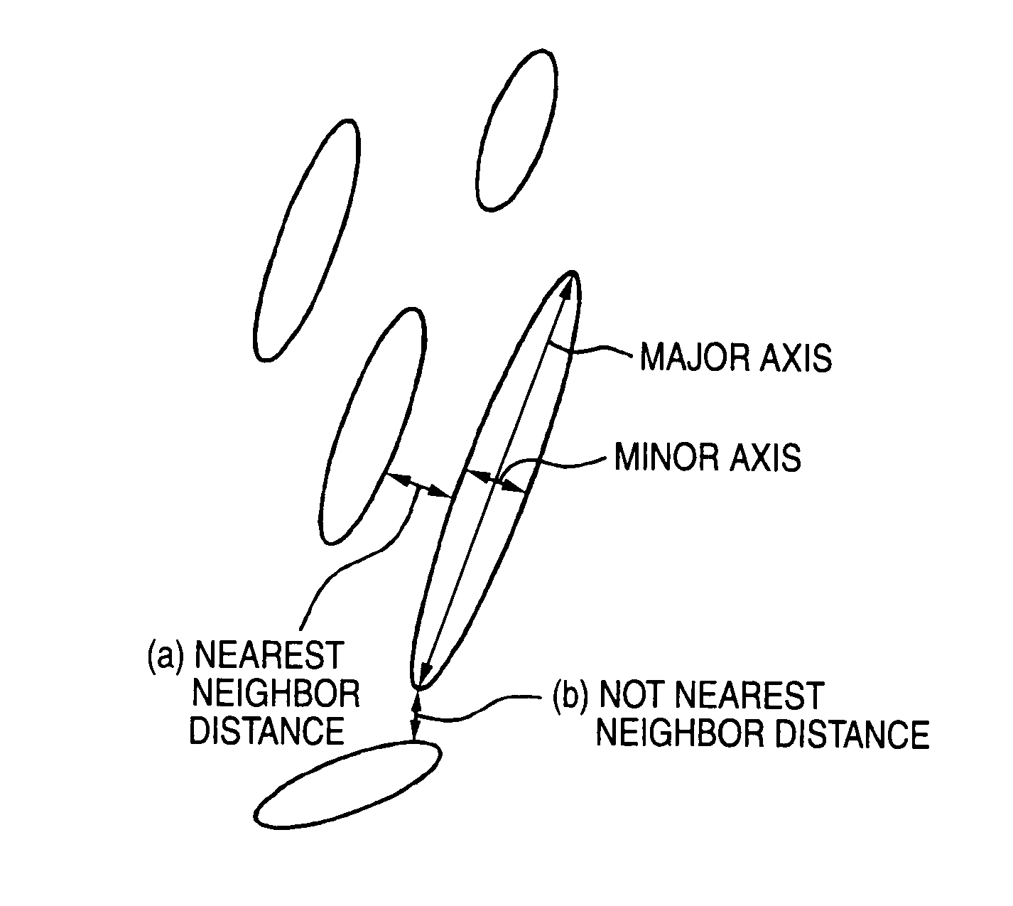
| nearest-neighbor distance | aaaaa | aaaaa |
| tensile strength | aaaaa | aaaaa |
Abstract
Description
Claims
Application Information
 - R&D
- Intellectual Property
- Life Sciences
- Materials
- Tech Scout
- Unparalleled Data Quality
- Higher Quality Content
- 60% Fewer Hallucinations
Browse by: Latest US Patents, China's latest patents, Technical Efficacy Thesaurus, Application Domain, Technology Topic, Popular Technical Reports.
© 2025 PatSnap. All rights reserved.Legal|Privacy policy|Modern Slavery Act Transparency Statement|Sitemap|About US| Contact US: help@patsnap.com