Radiographic apparatus

a technology of radiographic equipment and detectors, applied in the field of radiographic equipment, can solve the problems of heat generation, reduce the merit of compact, lightweight detection units,

Active Publication Date: 2011-02-15
CANON KK
View PDF25 Cites 28 Cited by
  • Summary
  • Abstract
  • Description
  • Claims
  • Application Information

AI Technical Summary

Benefits of technology

[0015]It is an object of the present invention to provide a radiographic apparatus which can control processing for a radiographic image in accordance with a radiographic form.
[0016]It is another object of the present invention to improve the reliability of a radiographic image detection unit and the safety of a radiographic apparatus in accordance with a radiographic form.

Problems solved by technology

Such a radiographic apparatus is electronic equipment, and hence includes many electronic parts indispensable to digitization, which inevitably pose the problem of heat generation, as compared with the conventional film / screen method.
This reduces the merit of the compact, lightweight detection unit.

Method used


Image

  • Radiographic apparatus
  • Radiographic apparatus
  • Radiographic apparatus

Examples


first embodiment

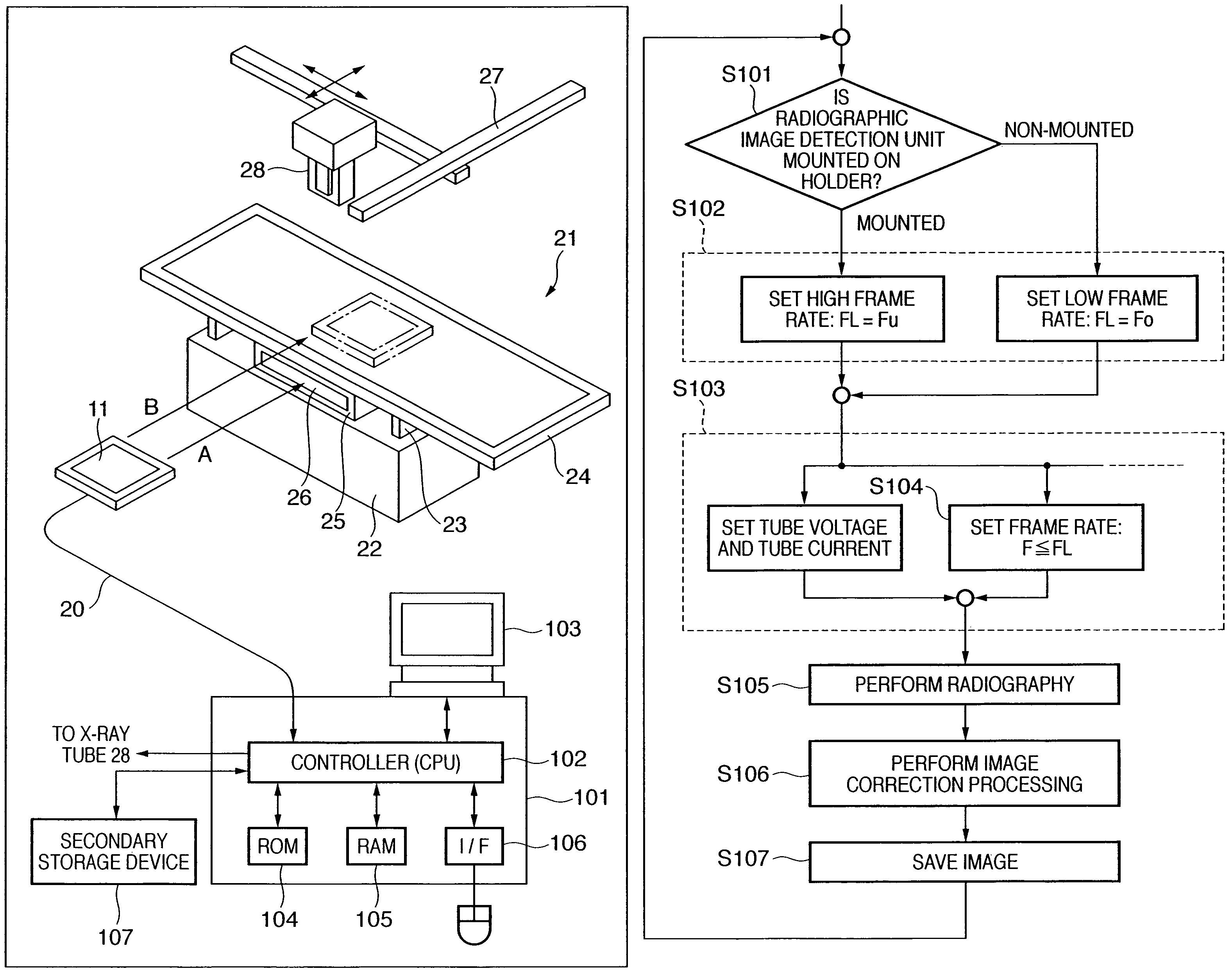
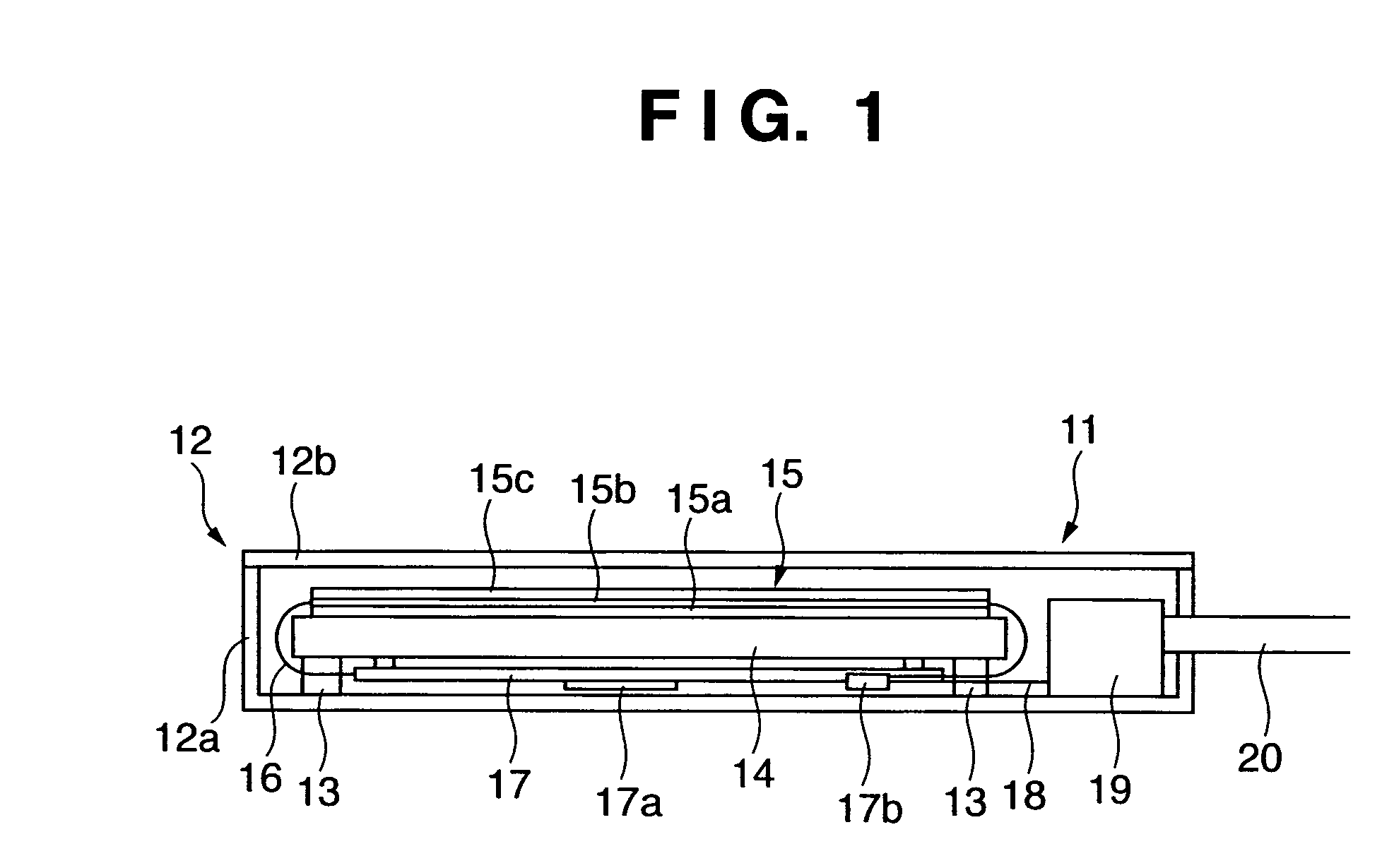
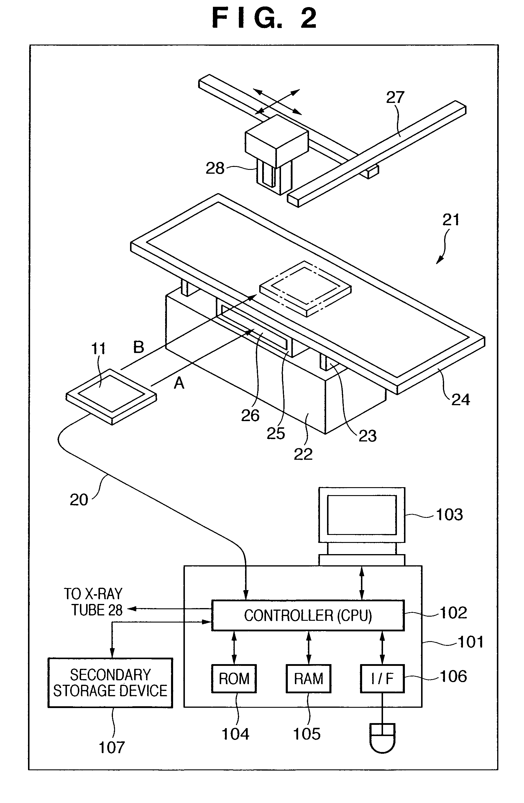
[0040]FIG. 1 is a sectional view of a radiographic image detection unit 11. The radiographic image detection unit 11 can be used independently as a cassette, and can be used in combination with various holders. A housing cover 12b made of a material having high X-ray transmission covers the X-ray incident surface of a housing body 12a. The housing body 12a and the housing cover 12b constitute a sealed housing 12. A metal base 14 is fixed to the housing body 12a through a support portion 13. An X-ray detection panel 15 on which a board 15a, photoelectric conversion elements 15b, and fluorescent screen 15c are stacked is placed on the base 14.

[0041]As a material for the board 15a, a glass plate is often used because it has no chemical action with a semiconductor element, has high resistance to the temperature of a semiconductor process, has dimensional stability, and the like. The photoelectric conversion elements 15b are formed in a two-dimensional array on the board 15a by a semicon...

second embodiment

[0067]The operation processing by a cooling mechanism and a controller 101 according to the second embodiment will be described next. FIG. 8 shows an operation window 90 displayed on a monitor 103 in the second embodiment.

[0068]FIG. 6 is a sectional view showing the cooling mechanism in a storage unit 25 according to the second embodiment. FIG. 6 shows a state wherein a radiographic image detection unit 11 is mounted in the storage unit 25.

[0069]The storage unit 25 houses a cooling mechanism comprising a heat dissipation fin 31 and heat dissipation rubber 32. An actuator 33 which is provided on a side of this cooling mechanism so as to be in contact with the mounted radiographic image detection unit 11 supports the cooling mechanism so as to allow it to be vertically movable. A side surface of the storage unit 25 has an opening portion 34 for intaking air. The bottom surface of the storage unit 25 has an opening portion 35 communicating with a radiographic stand body 22. A blower fa...

third embodiment

[0087]FIG. 9 is a view showing the arrangement of a radiographic apparatus according to the third embodiment. In the third embodiment, X-ray tubes 53 and 54 are mounted on a movable C-arm device 51 and a radiographic stand 52, respectively. In this case, the user prepares for radiography by mounting the radiographic image detection unit 11 on the C-arm device 51 or radiographic stand 52.

[0088]The distal end of the arm of the C-arm device 51 has a mount portion 59 for detachably supporting a radiographic image detection unit 11. The mount portion 59 has a cooling mechanism for cooling a radiographic image detection unit 55 as in the second embodiment. The radiographic image detection unit 11 acquires a radiographic image by detecting X-rays applied from the X-ray tube 53.

[0089]A controller 56 connects to the C-arm device 51. The controller 56 has functions similar to those in the first and second embodiments. The C-arm device 51 is mainly used for radiography of a moving image such a...


PUM


Abstract

In order to improve the reliability of a radiographic image detection unit and the reliability of a radiographic apparatus, when it is not detected that the radiographic image detection unit is mounted on a support portion or a cooling portion, processing for restricting radiography of a moving image is executed.

Description

TECHNICAL FIELD[0001]The present invention relates to a radiographic apparatus using, for example, a flat panel sensor.BACKGROUND ART[0002]Conventionally, apparatuses which apply radiation to targets, detect the intensity distributions of radiation transmitted through the targets, and obtain radiographic images of the targets have been widely and generally used in the fields of industrial nondestructive testing and medical diagnosis. As a general method for such radiography, a film / screen method using radiation is available. This is the method of performing radiography by using a combination of a photosensitive film and a phosphor having sensitivity to radiation.[0003]In this method, rare-earth phosphor sheets which emit light upon application of radiation are held in tight contact with the two surfaces of a photosensitive film, and the phosphor sheets convert radiation transmitted through a subject to be radiographed into visible light. The latent image formed on the photosensitive...

Claims


Application Information

Patent Timeline
Patent Type & Authority Patents(United States)
IPC IPC(8): H05G1/58H05G1/64
CPCA61B6/4216A61B6/4283A61B6/4488A61B6/467A61B6/54A61B6/586G03B42/04A61B6/00
Inventor WATANABE, TETSUO
Owner CANON KK
Why Eureka
Try Eureka