Transformer

a transformer and transformer technology, applied in the field of transformers, can solve the problems of short circuit damage, prone to breakage, etc., and achieve the effects of improving stability, improving quality and reliability, and easy and fast troubleshooting and repair

Inactive Publication Date: 2011-02-22
LOGAH TECH CORP
View PDF4 Cites 6 Cited by
  • Summary
  • Abstract
  • Description
  • Claims
  • Application Information

AI Technical Summary

Benefits of technology

[0014]An object of the present invention is to provide an improved transformer that has a buffer region so that the division point formed by the secondary wire may be held in the buffer region and that the secondary wire would not be prone to breakage. Therefore, quality and reliability may be improved.
[0015]Another object of the present invention is to provide an improved transformer in which the division point is held in the buffer region so that the secondary wire is not prone to breakage. Moreover, thanks to the buffer region, troubleshooting and repair may be done easily and quickly.
[0016]A third object of the present invention is to provide an improved transformer in which the secondary wire would not be affected or pressed against by the primary wire and hence would not be prone to breakage. Therefore, stability is improved.
[0017]A fourth object of the present invention is to provide an improved transformer in which the thicker secondary wire would not be in twine with or tangled up with the other segment of the secondary wire in the secondary winding partitions so that the short circuit of the secondary wire may be avoided.
[0018]To reach these objects, the improved transformer of the present invention is disclosed. The improved transformer of the present invention comprises a main body and a secondary winding. The main body has a primary winding partition, several secondary winding partitions and two end portions. Several leads are disposed in either end portion. A wire-guiding area is formed in a sunken area in the primary winding partition and a buffer region is formed between the primary end portion and the primary winding partition. The primary winding and secondary winding are wound around the iron core on the main body. One end of the secondary wire runs from the secondary winding partitions to the wire-guiding area. Before the secondary wire goes into the buffer region, the secondary wire is folded for several times and then is twisted and rolled for several turns to make the secondary wire thicker. Then the secondary wire goes into the buffer region and then is connected to one of the primary leads. After the winding of the secondary wire is completed, the winding of the primary wire may be started to wind the primary wire around the iron core in the primary winding partition. With the wire-guiding area, the secondary wire would not be affected or pressed against by the primary wire and hence would not be prone to breakage. With the buffer region, the division point is held in the buffer region and hence would not be prone to breakage.

Problems solved by technology

Especially, in small-size step-down transformer, a very fine wire is usually used for the winding; therefore, the wire is prone to breakages (which may lead to a short circuit) and damages if the winding is not done meticulously.
1. The secondary wire 42 is usually a thinner wire and has to pass the primary winding partition 31. Then the primary wire 41 is wound around the core on the primary winding partition 31. Therefore, the secondary wire 42 is pressed and squeezed by the primary wire 41 and hence is prone to breakage and damage.
2. Before the secondary wire 42 goes into the buffer region, the secondary wire 42 is folded for several times and then is twisted and rolled for several turns to make the wire thicker. Therefore, a division point 421 is formed and is prone to breakage because it is pressed against and squeezed by the primary wire 41.
Thus, efficiency in assembly is impeded.
In addition, because the division point 421 is buried under the primary wire 41, troubleshooting can not be carried out easily.
This may cause a short circuit of the secondary wire 42.
Such short circuit may cause the transformer to burn.

Method used


Image

  • Transformer
  • Transformer
  • Transformer

Examples


Embodiment Construction

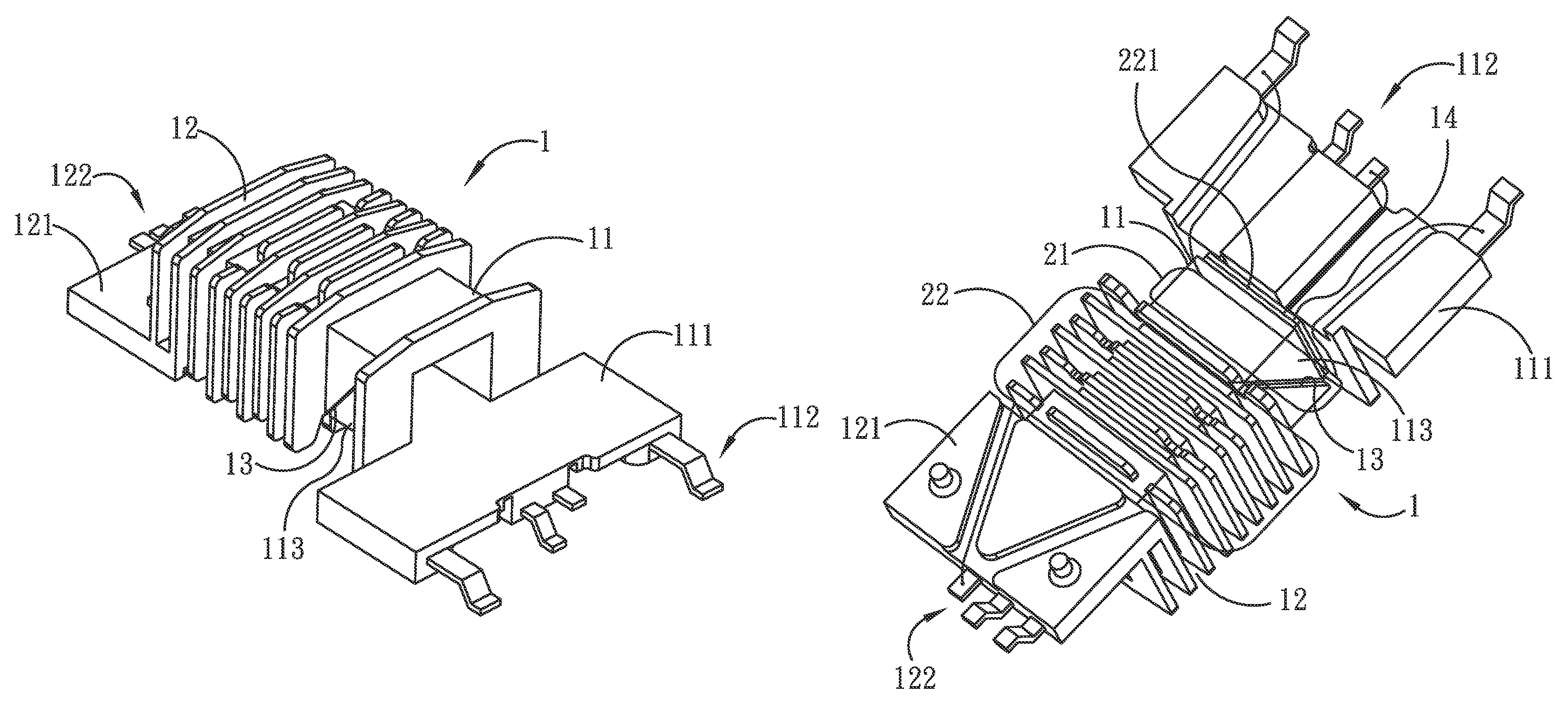
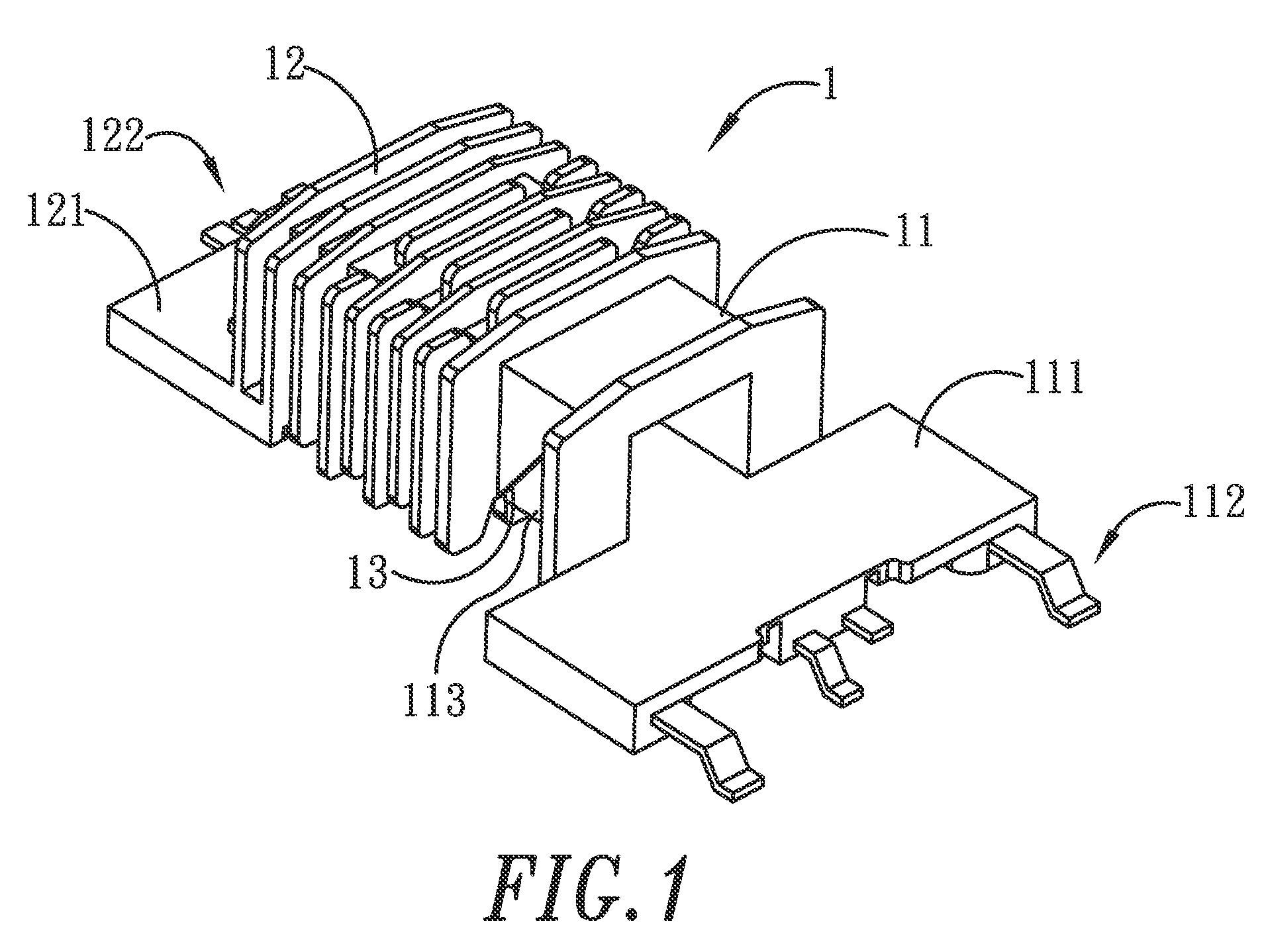
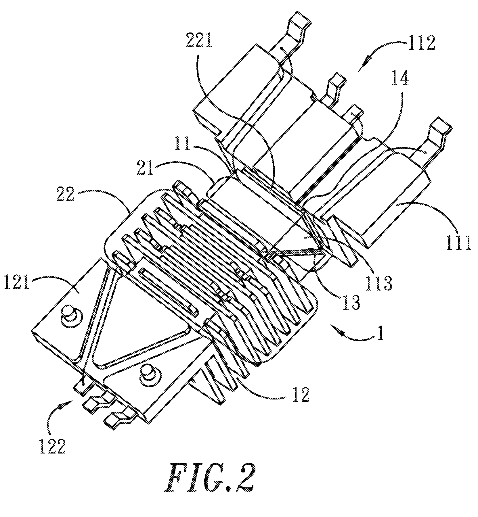
[0024]Please refer to FIGS. 1 to 3, which illustrate the improved transformer of the present invention. The improved transformer of the present invention comprises a main body 1 and a secondary winding 22. The main body 1 has a primary winding partition 11 and several secondary winding partitions 12. A primary end piece 111 is disposed near the primary winding partition 11, and several primary leads 112 are provided in the proximal edge of the primary end piece 111. Similarly, a secondary end piece 121 is disposed near the secondary winding partitions 12, and several secondary leads 122 are provided in the distal edge of the secondary end piece 121.

[0025]A step-like sunken area 113 is formed on the primary winding partition 11. A wire-guiding area 13 is formed between in the sunken area 113. A buffer region 14 is formed between the primary end piece 111 and the primary winding partition 11. The buffer region 14 is formed in a sunken region between the primary end portion 111 and the...


PUM

PropertyMeasurementUnit
areaaaaaaaaaaa
currentaaaaaaaaaa
electrical energyaaaaaaaaaa

Abstract

A transformer includes a main body and a secondary winding. The main body has a primary winding partition, several secondary winding partitions and two end portions. Several leads are disposed in either end portion. A wire-guiding area is formed in a sunken area in the primary winding partition and a buffer region is formed between the primary end portion and the primary winding partition. The secondary winding is wound around the core on the secondary winding partitions. One end of the wire runs from the secondary winding partitions to the wire-guiding area. Before the secondary wire goes into the buffer region, the secondary wire is folded for several times and then is twisted and rolled for several turns to make the secondary wire thicker. Then the secondary wire goes into the buffer region and then is connected to one of the primary leads. Due to the wire-guiding area and buffer region, the secondary wire would not be affected or pressed against by the primary wire.

Description

BACKGROUND OF THE INVENTION[0001]1. Field of the Invention[0002]The invention generally relates to an improved transformer. More particularly, the invention relates to an improved transformer, in which a buffer region is used to hold the division point formed by the secondary wire so that the secondary wire would not be affected or pressed against by the primary wire and hence would not be prone to breakage. Therefore, quality and reliability of the transformer may be improved.[0003]2. Description of the Prior Art[0004]The coil type transformer has been around for more than 100 years. Many improvements and modifications have been made to improve the coil type transformer. Despite these improvements and modifications, the coil type transformer operates according to the same physical principle, mutual induction.[0005]In the coil type transformer, mutual induction occurs if an emf is induced in a coil because of current changes in a second coil. A primary coil and the secondary coil ar...

Claims


Application Information

Patent Timeline
Patent Type & Authority Patents(United States)
IPC IPC(8): H01F27/30
CPCH01F5/04H01F27/325H01F2005/022A61P1/00A61P3/04A61P9/10
Inventor LU, CHIH-PINGCHIANG, CHIH-SHEN
Owner LOGAH TECH CORP
Why Eureka
Try Eureka